I'm very familiar with the S2F-1 Tracker simply because the JMSDF used to operate quite a number of the Tracker for a long time
and I did take a lot of photos of the JMSDF Trackers during the 1970s-1980s.
I particularly liked the engine sound (especially its start-up) of the Tracker.
So, the Tracker is surely one of my favourite aircraft type.
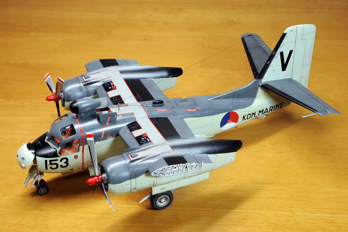
I was so glad that Kinetic released a 1/48 kit of the S2F-1 Tracker several years ago, and I decided to finish this Tracker model in the Royal Netherlands Navy markings
simply because I like the paint scheme and the Dutch national insignia.
USN markings on the Tracker is too ordinary for me.
日本の飛行機マニアにとって、S2F-1トラッカーはとても馴染みの深い機種です。
かつて海上自衛隊が多数のトラッカーを運用しており、小生も沢山の写真を撮る機会がありました。
あの独特のエンジン音が大好きで、特にその始動時の音は今でも懐かしく思い出されます。
長らくトラッカーはマトモなキットに恵まれず、一般論としては1/72で古いハセガワのキットがあったぐらいです。
よって、数年前にキネティックが1/48でトラッカーの新製品を発売した時は大いに喜びました。
(まあ実際には、あまりお薦めできるようなキットではなかった、と今になってわかりましたが。)
1970年代始めに、当時コダクロームスライドを交換していたオランダのマニアから素晴らしいオランダ海軍のトラッカーのスライドを受け取り、大感激したのを今でも良く覚えています。
だから、このトラッカーは始めから『オランダ海軍』のマーキングで仕上げようと決めていました。
まあ米海軍や海自のマーキングでは、自分にとって余りにも平凡過ぎるとも思ったからです。

A photo at left shows all the after-market parts/decals to be used for my Tracker project.
I did not use all of them, but they include the following items.
(1) Decals
*, Flevo Decal FD48-009
*, Dutch Decal DD48044
(2) Eduard photo etched parts
*, Bomb bay #48699
*, Interior #49564
*, Exterior #48701
*, Undercarriage #48700
(3) Quickboost Resin parts
*, Propellers QB48569
*, Tail Wheel QB48530
*, Engines QB48512
*, Pylons QB48531
(4) Aires resin Wheels #4593
今回使用したアフターマーケットの部品やデカールは上記(1)から(4)に記載しました。
なけなしの年金を投げ打って、これらのアフターマーケット部品を購入しましたが、
S2F-1には適用されないモノや、質が悪くて使えなかったモノもあり、かなり無駄な出費が多かったです。
反省しきり。
You can enlarge all the photos on this page by clicking on images.
クリックで本ページ内の全ての画像を拡大出来ます
Cockpit & Cabin 操縦室とキャビン
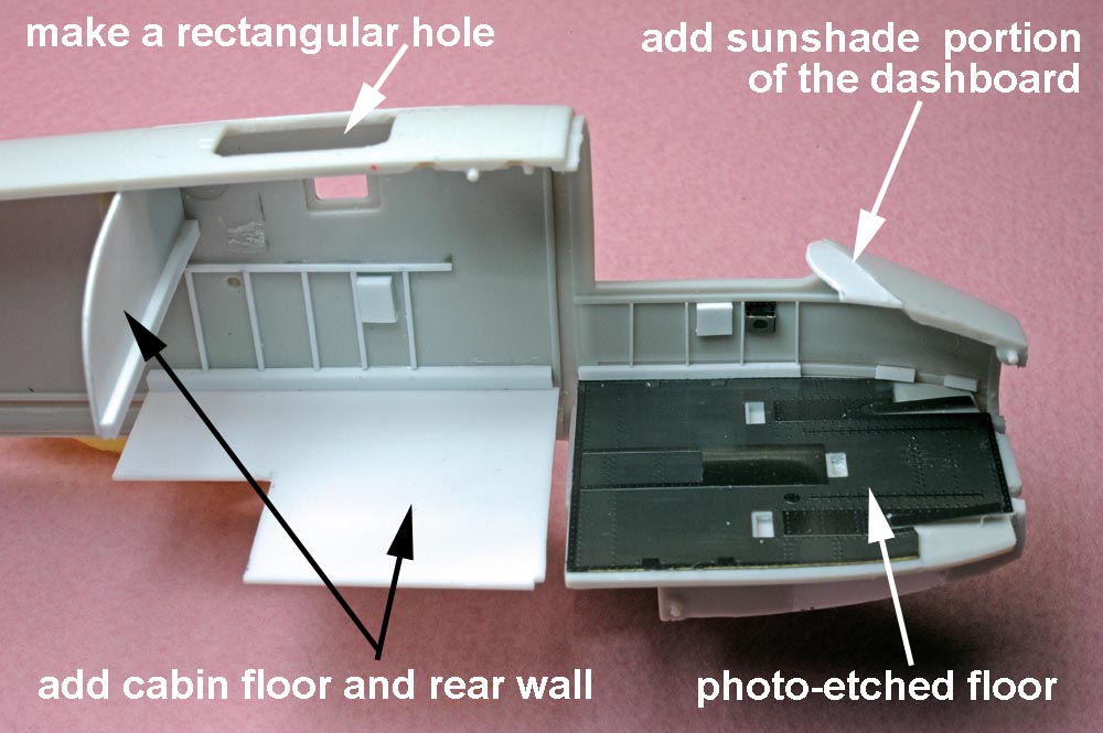

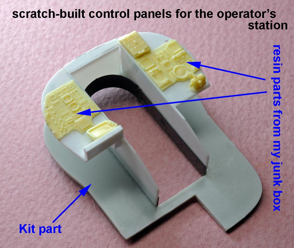
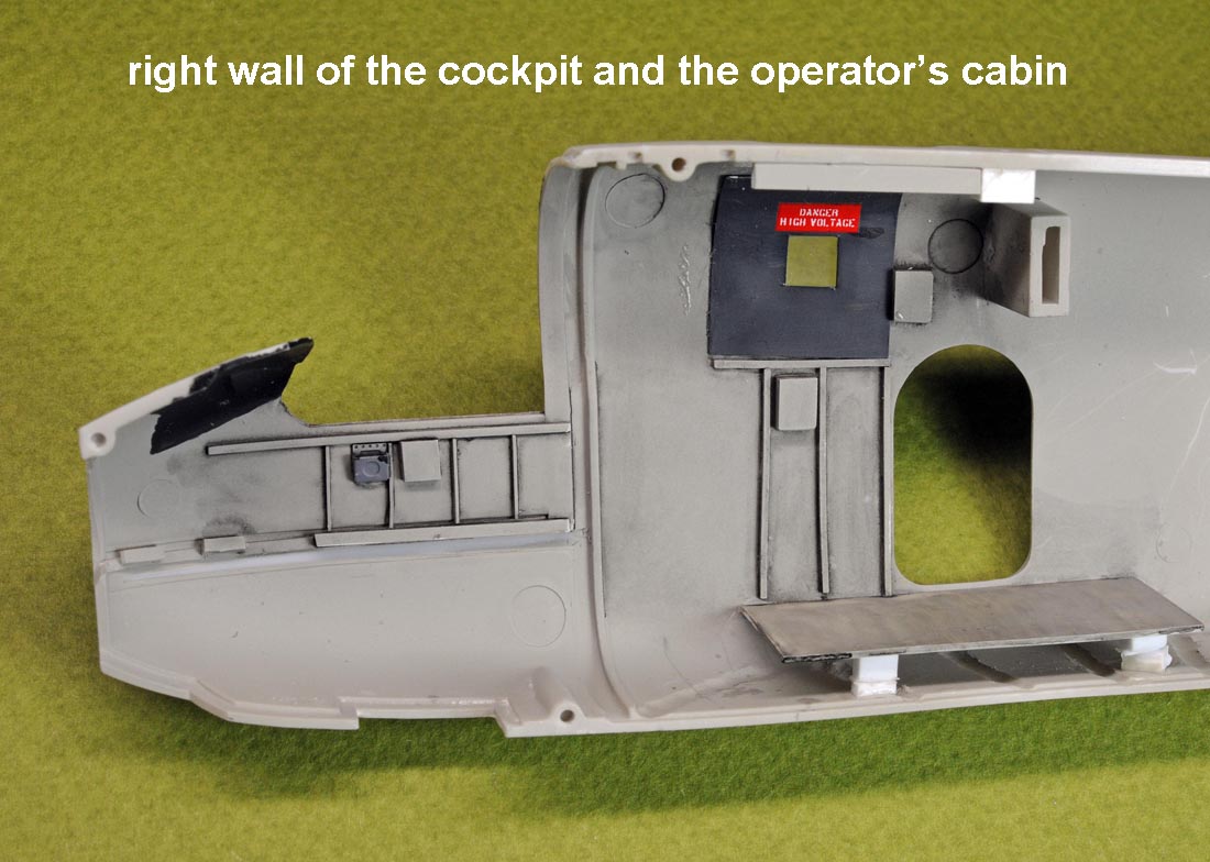
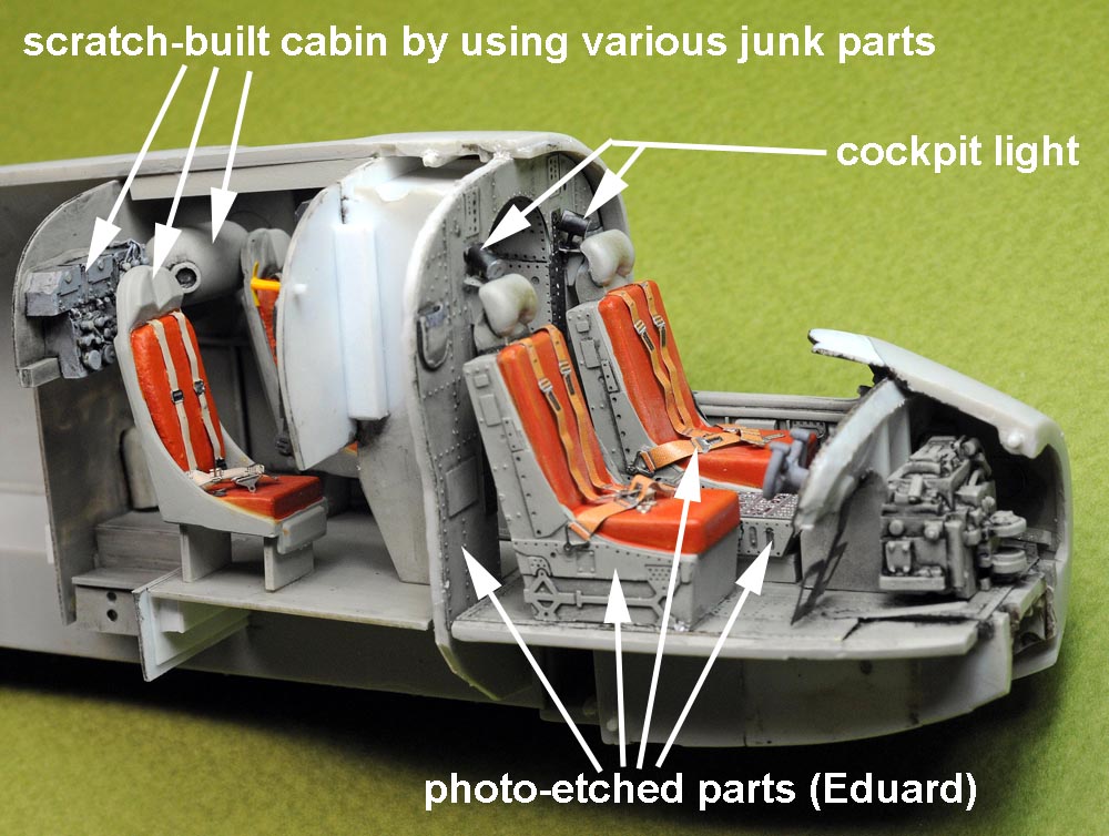
(above 4 photos),I scratch-built operator's station in the cabin behind the cockpit including its floor, side-wall, console and escape hatch(placed in open position).
I used Eduard's photo-etched parts for the cockpit floor and the rear wall of the cockpit as shown on the above photos.
【上4枚】、操縦室の後ろにあるオペレーター用キャビンを自作して、天井部にある脱出ハッチを開けることで、内部をのぞき込めるようにしたいと思いました。
でも実際に完成してみると、折り畳んだ主翼が邪魔して、結局キャビン内はほとんど覗き込めないことになりました。
キャビンの側壁にデカールまで貼って頑張ったんですが、それも無駄でした。

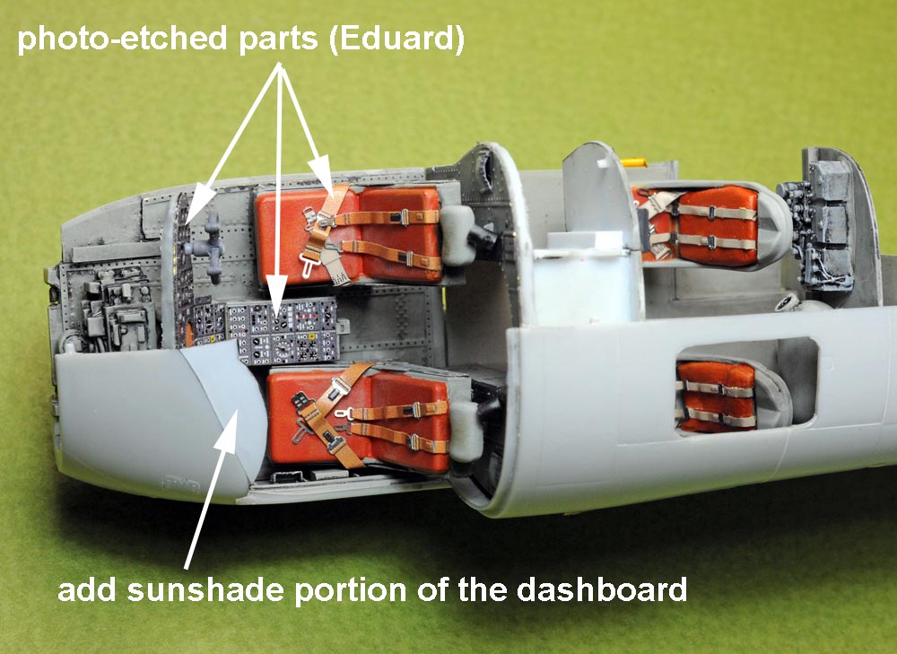
(above 4 photos),The kit part does not have a sunshade portion (anti-glare panel) of the dashboard, so I added it as shown on the above photo.
I used several colored photo-etched parts in the cockpit including instrument panel and floor console.
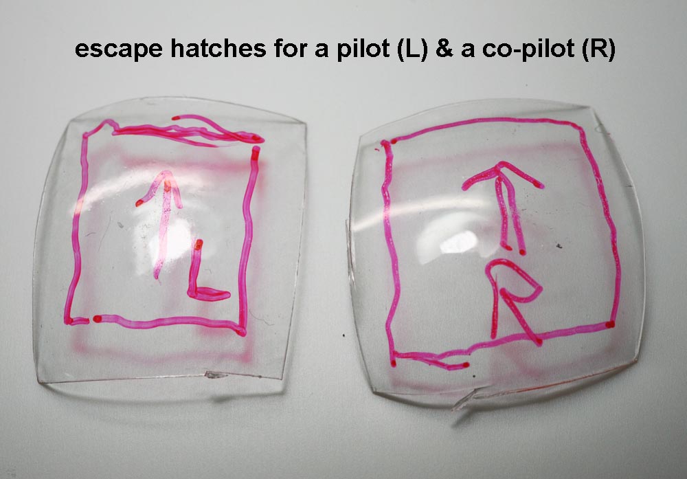
A photo at bottom right shows clear plastic parts molded by heat-press process for the escape hatches on top of the cockpit.
【上4枚】、このキットには計器盤上部の日除け用張り出しが無いので、樹脂板で作りました。
コックピット内部はEduardの色付きエッチング部品を多用しています。
右下の写真は、操縦室の天井部にある脱出用ハッチのために絞り出した透明部品です。
最も、操縦室内を覗き込めるように、ハッチは開けて取り付けるので、外からはほとんど見えない部品です。
.
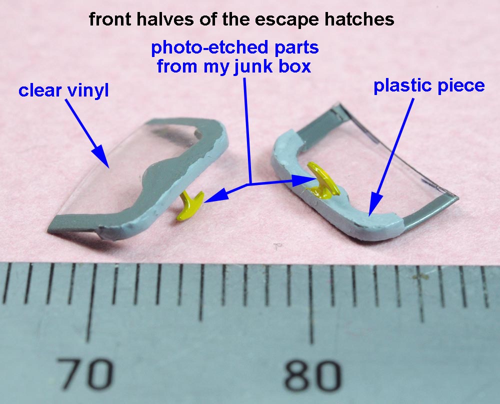
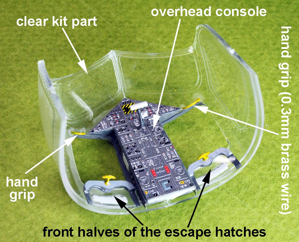
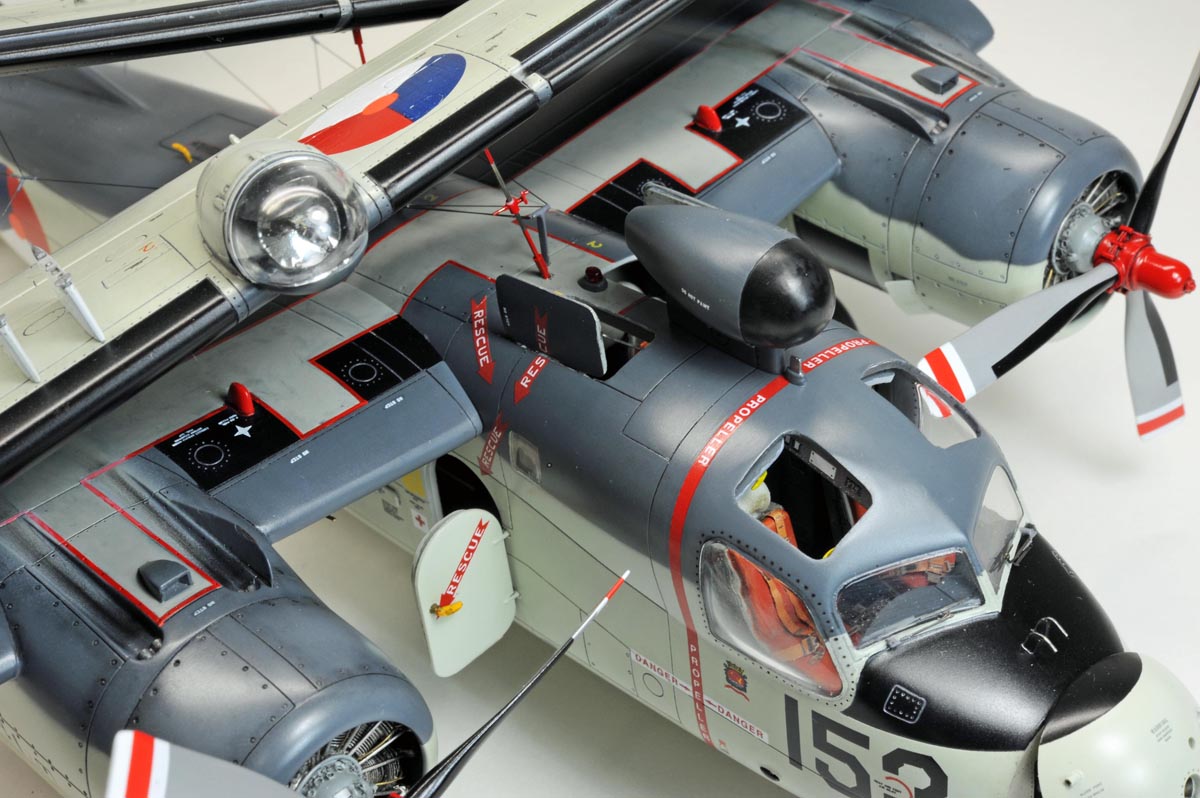
(above 4 photos),A photo at top left shows a front half of the escape hatch to be placed above the pilot/co-pilot seat in open position.
This hatch can be opened by sliding it rearwards by pulling the yellow T-shaped handle.
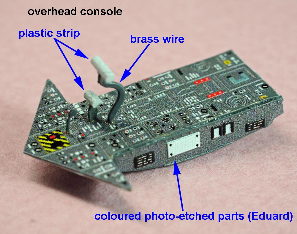
A photo at top right shows an overhead console assembly including throttles.
A photo at bottom left shows a canopy assembly including escape hatches placed in the open position.
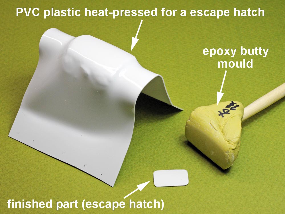
A photo at bottom right shows how I mold the escape hatch for the operator in the cabin.
【上4枚】、
左上の写真は操縦士用の脱出ハッチです。開けた状態でキャノピー後部に取り付けるので、ハッチの前半分だけ作りました。
T字型の黄色い部品は、ハッチを後方にスライドさせる時に操作するハンドルです。
右上の写真はオーバーヘッド・コンソールですが、Eduardの色付きエッチング・パーツにスロットル等のレバー類を追加しました。
左下はキャノピー内部の写真です。前方には脱出時に使う黄色い取っ手を付けました。又、後方天井部には脱出ハッチを開けた状態で接着しました。
左下はキャビン内のオペレーター用脱出ハッチを絞り出した時の写真です。
.
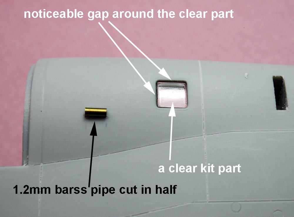
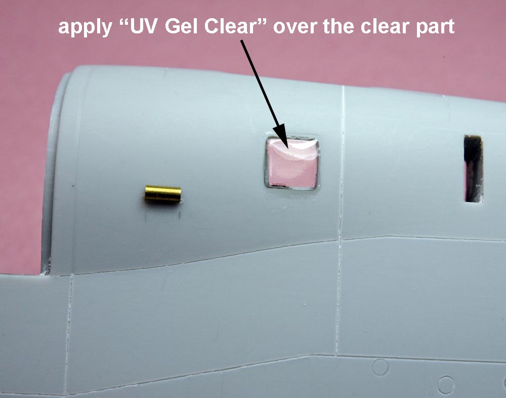
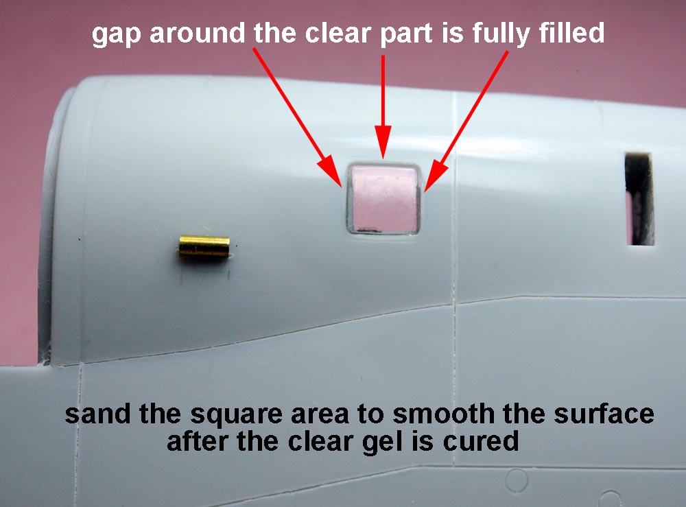
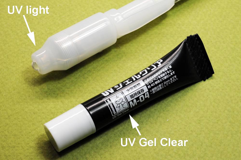
(above 4 photos),These photos show how I filled up the gaps around the square clear part (cabin window).
I applied "UV Gel Clear"(see photo at bottom right) around the clear part at first(see photo at top right).
After the gel is cured, I sanded over the clear part and the gap is smoothly filled with clear material around the window (see photo at bottom left).
【上4枚】、
ガイアノーツの"UV Gel Clear"を使って、透明部品(四角のキャビン窓)の周囲にできた隙間を埋めるプロセスを3枚の写真(左上→右上→左下)に撮りました。
この場合ではかなりキレイに隙間を透明素材で埋めることができました。ご参考まで。
.
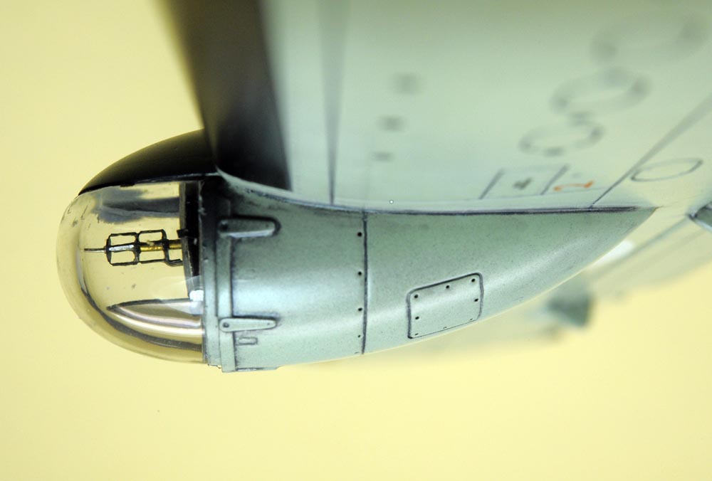
Hinged Nose 機首部
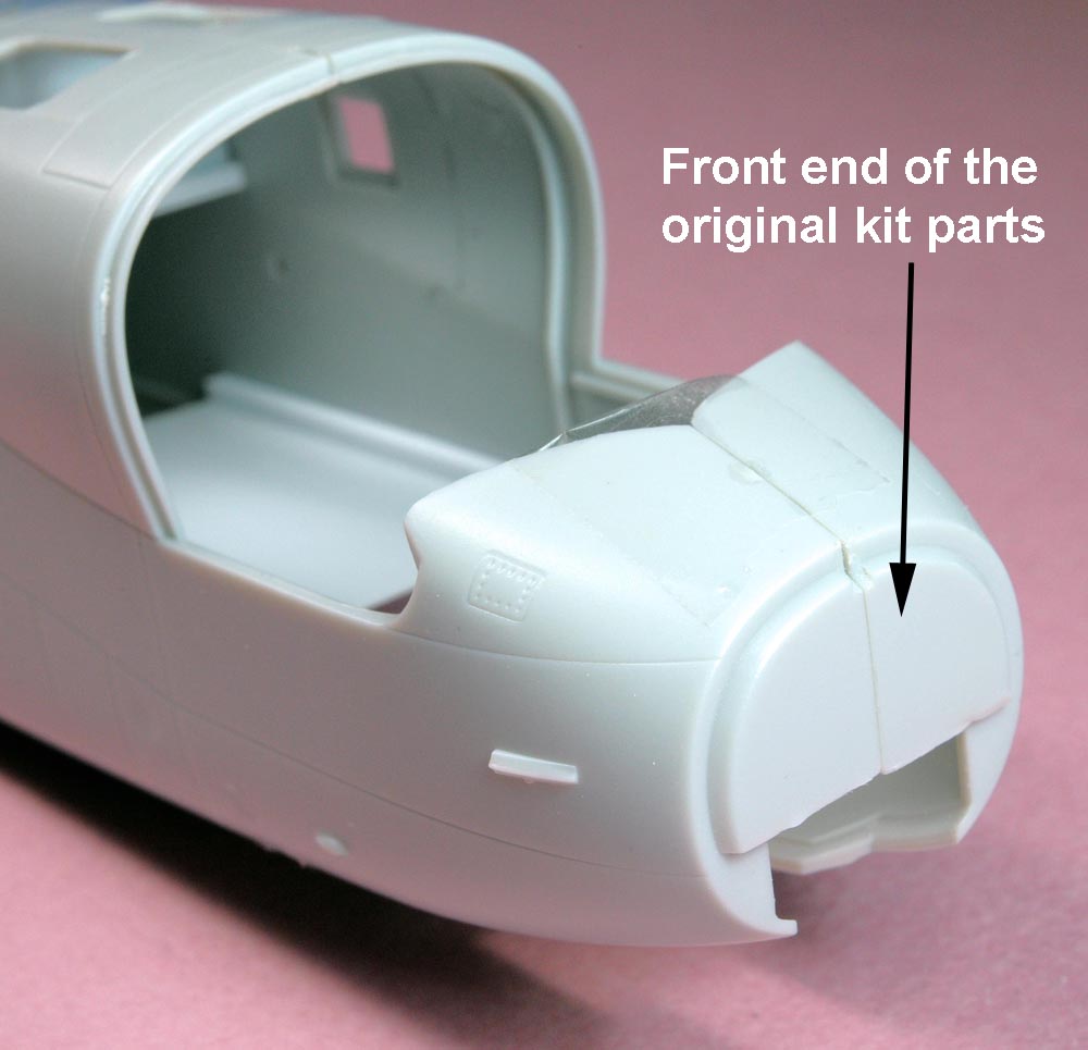
(above 4 photos),
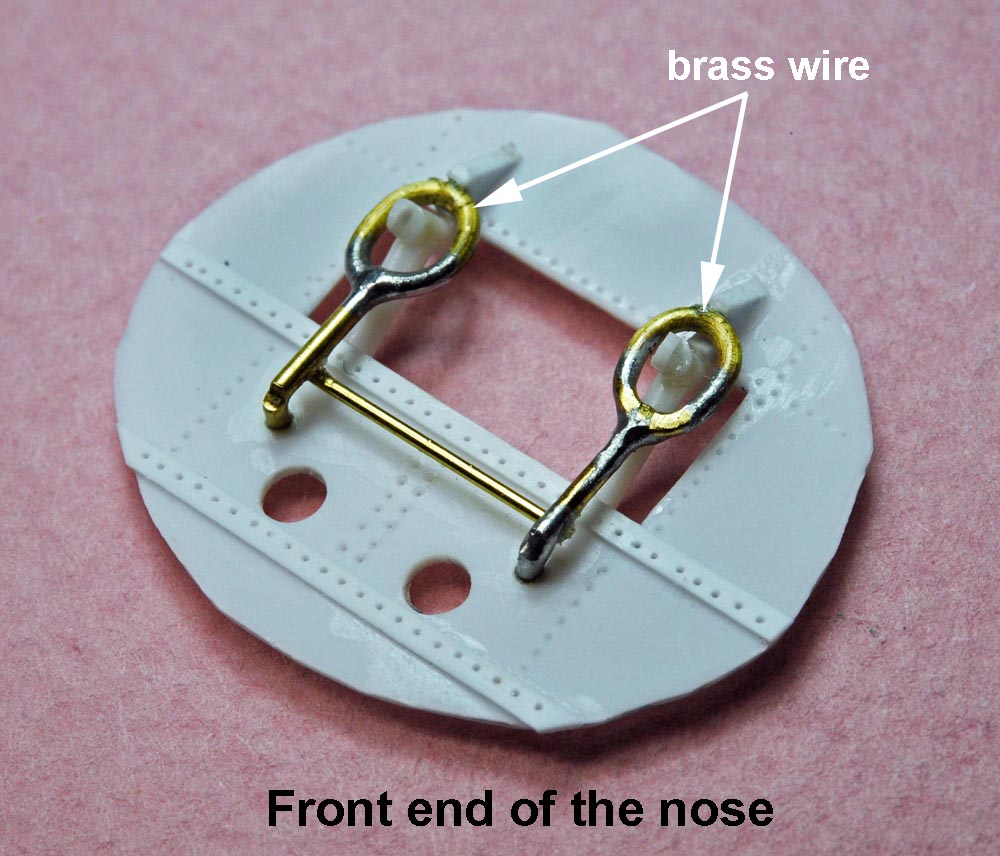
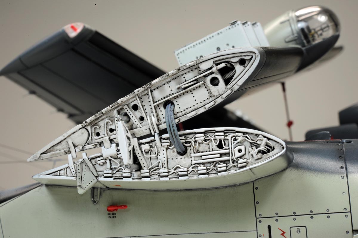
I planned to place the nose cone in open position, and so I serched for some close-up photos showing the details of the front end of the fuselage
and the inside surfaces of the hinged nose.
I scratch-built all details based on the photos I found on the internet.
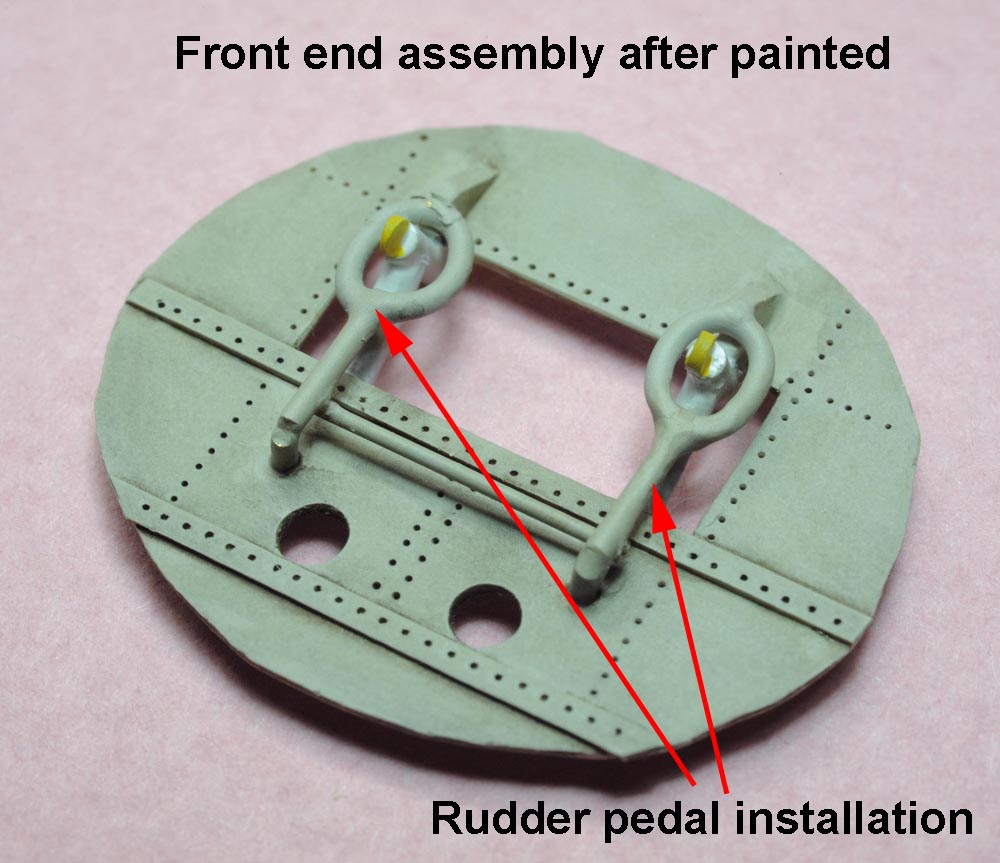
Rudder pedal installation is clearly seen on the front end of the fuselage as shown on the photos above.
【上4枚】、トラッカーの実機写真を見ると、機首コーン部を開けている写真が多く見受けられます。
それを模型で再現させるために、コーン内部の細部写真をネットで探すことになりました。
数枚の鮮明な写真が見付かったため、それを参考にして、機首コーン内部を樹脂板や真鍮棒などで作り込みました。
上の写真の如く、操縦系統のメカの一部が機首コーンを開けると露出しています。
.

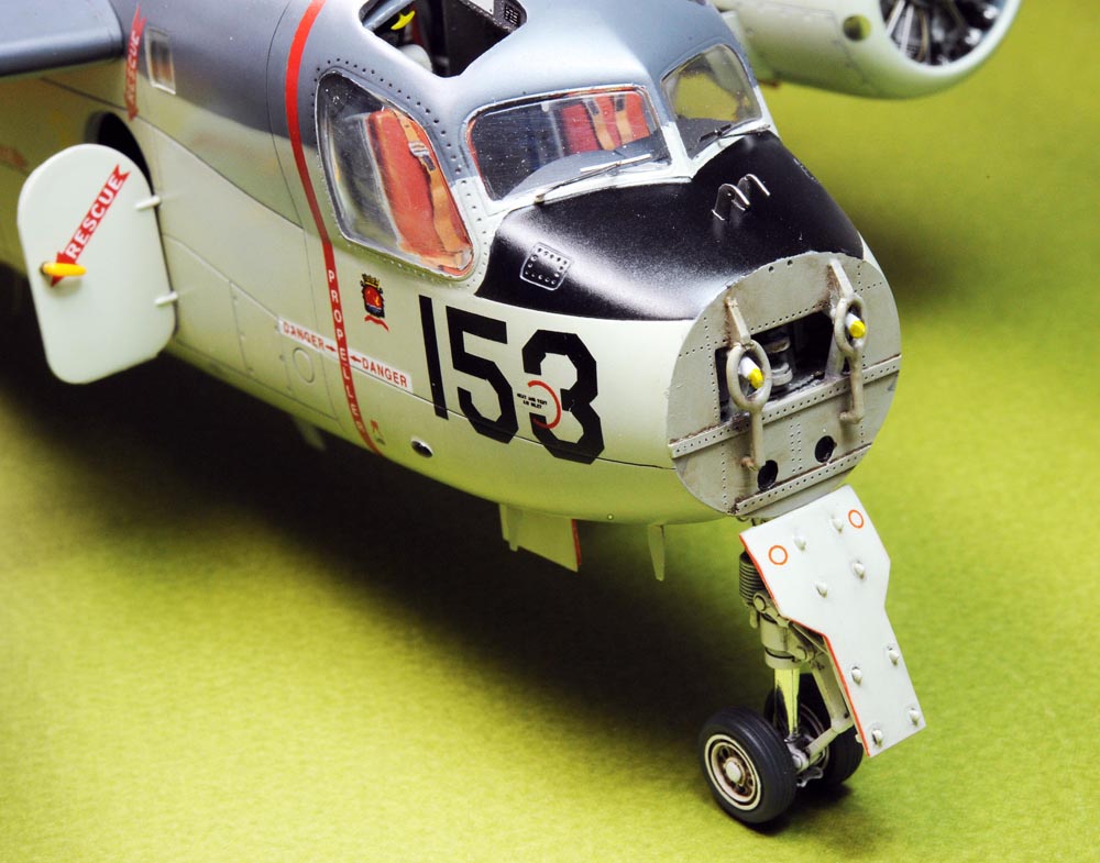
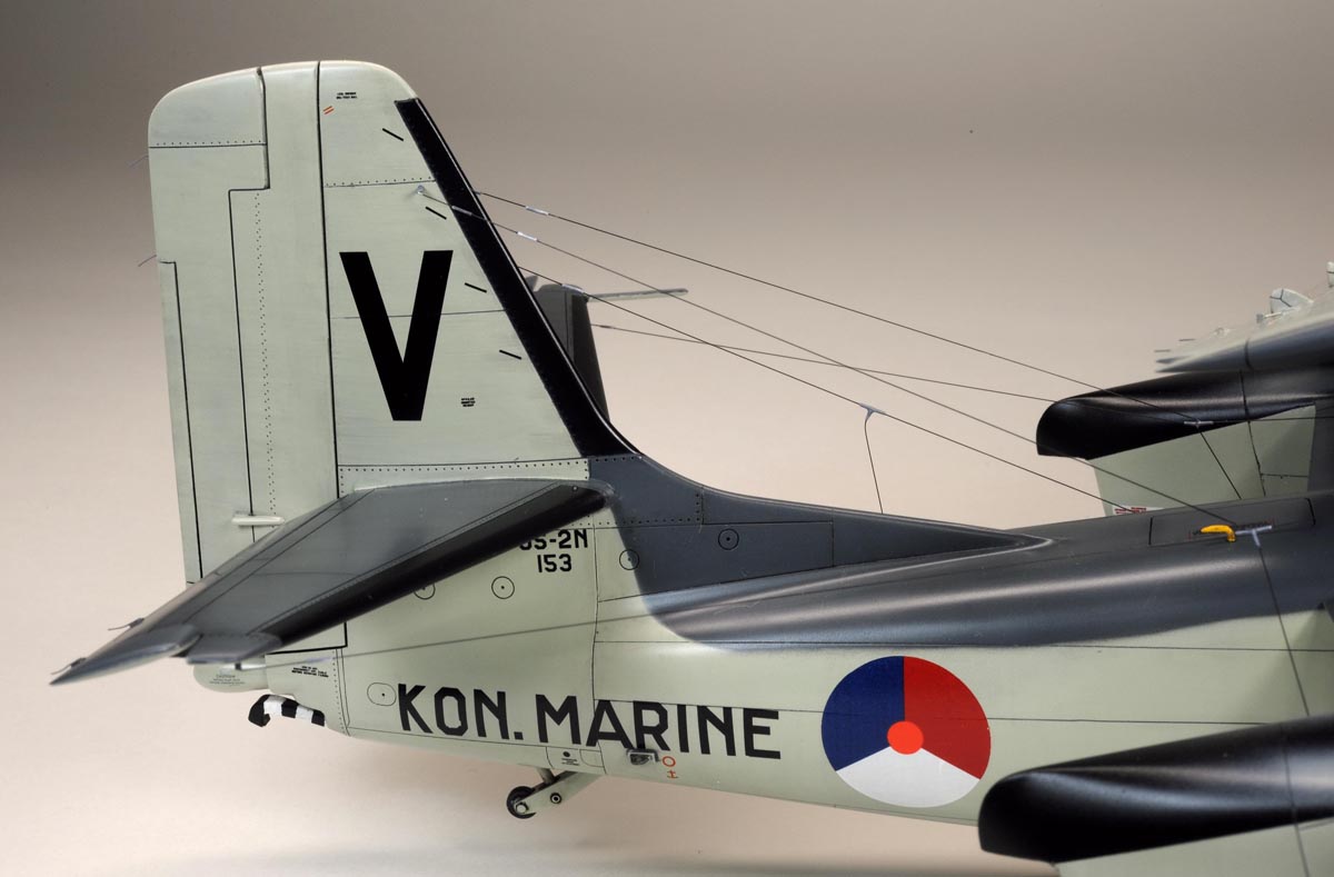
 (above & at left),
The kit carrys three variants of the hinged nose and I picked the one which closely resembles the Dutch S2F nose.
I used a crystal bead for the taxi light, which I found at a bead shop in Tokyo.
I scratch-built inside structure of the hinged nose as show on the photo at left.
(above & at left),
The kit carrys three variants of the hinged nose and I picked the one which closely resembles the Dutch S2F nose.
I used a crystal bead for the taxi light, which I found at a bead shop in Tokyo.
I scratch-built inside structure of the hinged nose as show on the photo at left.
【上3枚】、このキットには3種類の機首コーンが入っており、バリエーション展開にえらく積極的です。
その3種類の中からオランダのS2F-1に一番似ているモノを選びました。
機首のタキシー・ライトはビーズ屋さんで見付けたピカピカするビーズを使いました。
機首コーンの内部は、探し当てた実機写真を参考に樹脂片と真鍮とアルミ・パイプなどで作り込みました。
.
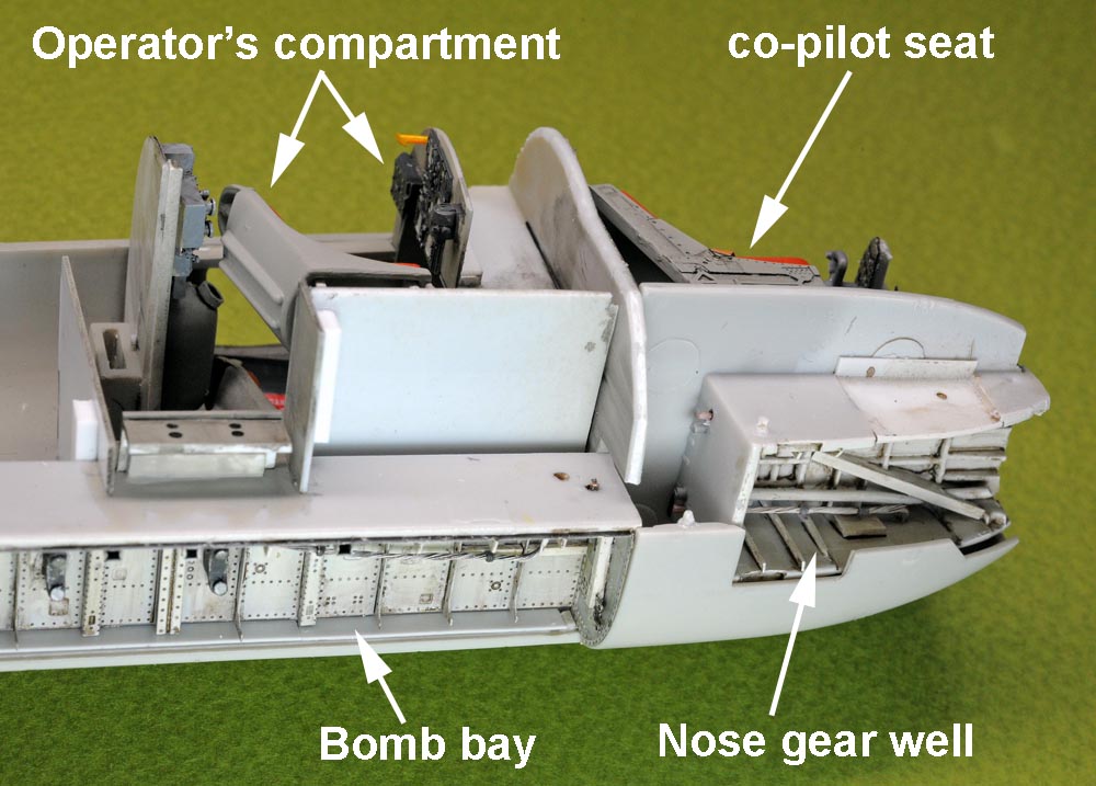
Nose Gear Well 前脚収納庫

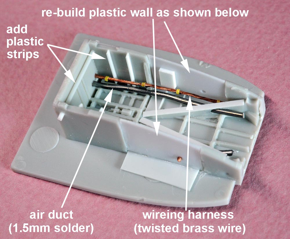
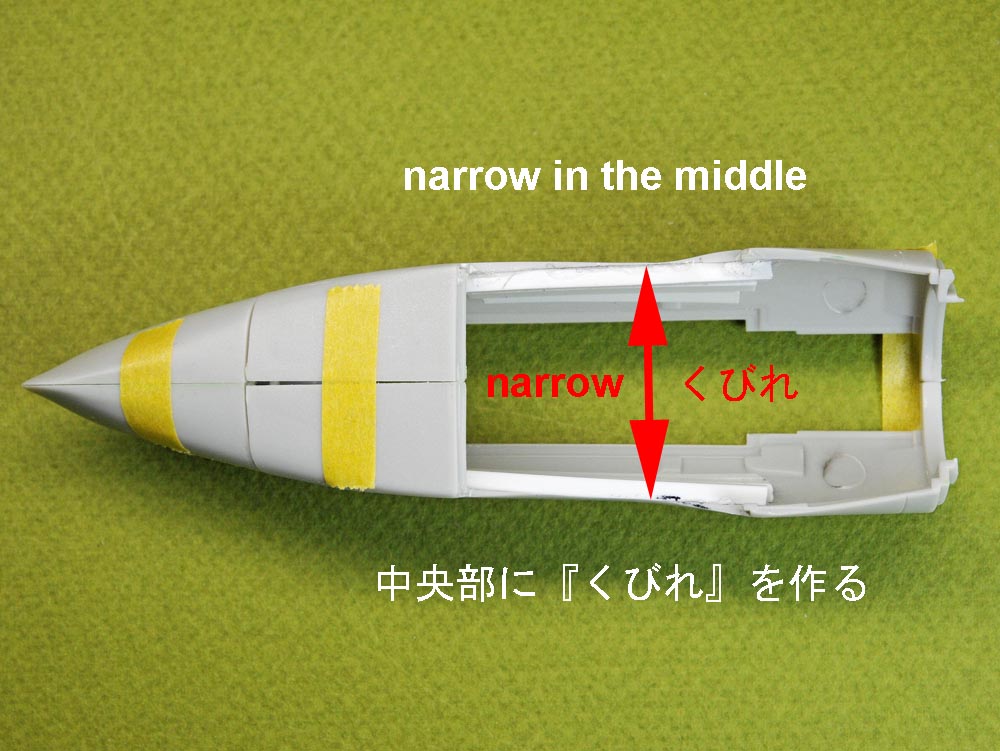
(above 2 photos), Original kit part for the nose gear well is molded in the wrong shape, and I had to reshape the side wall of the nose gear well.
I also add some details (duct, wiring harness, etc.) as shown on the photo at above right.
【上2枚】、
キット部品では収納庫の形状が実機と異なる(中央が狭まっていた)ので、やむ無く中央部の縦壁を切り取って、壁を真っ直ぐに作り直しました。
と同時に、空気ダクトや電気配線等のディテールを金属素材や樹脂板で作り込みました。
.
Bomb Bay 爆弾槽
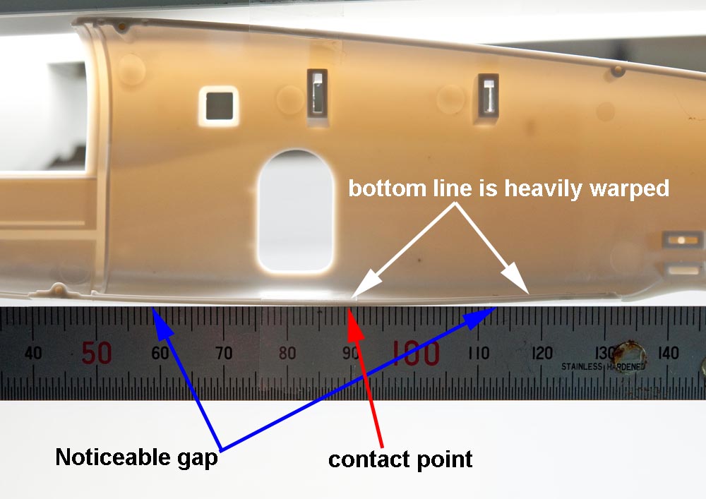
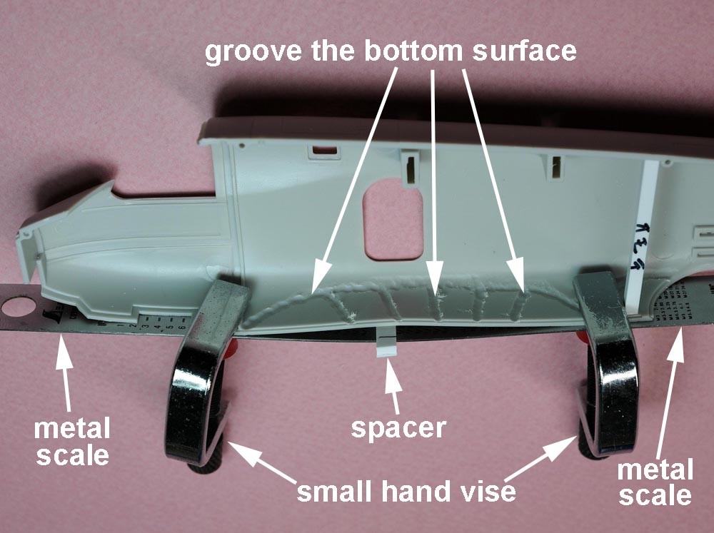
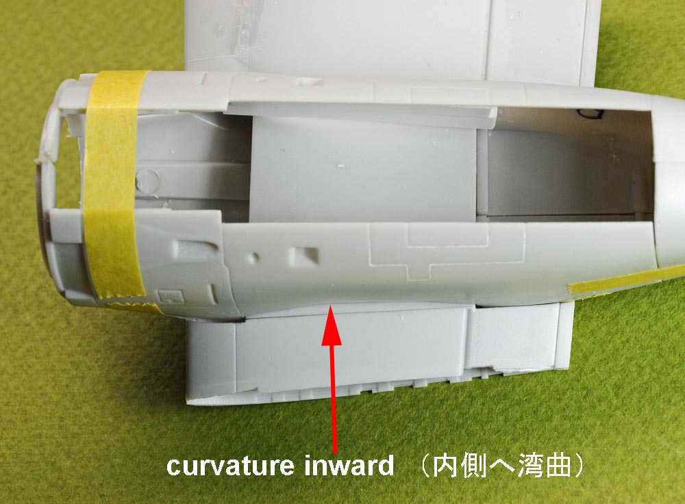
(above 2 photos),The bottom surface of the mid-fuselage (right half) around the bomb bay is permanently warped downwards as shown on the photo at above left.
So, I forcedly transformed the warped area to the straight and flat shape as shown on the photo at above right.
To make it easier and quicker, I applied heat to the warped surface by using a hair dryer.
【上2枚】、
上左の写真の如く、胴体部品(右半分)の底面中央が下側に湾曲しており、爆弾槽がきちんと収まらないことが判明しました。
そこでやむを得ず、上右の写真の如く、強制的に逆方向に湾曲させて、底面が真っ直ぐになるよう変形させました。
湾曲面中央部にスペーサーを噛ませて、その両端を小型万力で押さえ込む方法です。
変形を容易にするために、内側に溝を彫り強度を弱め、更にドライヤーで熱を当てました。
.
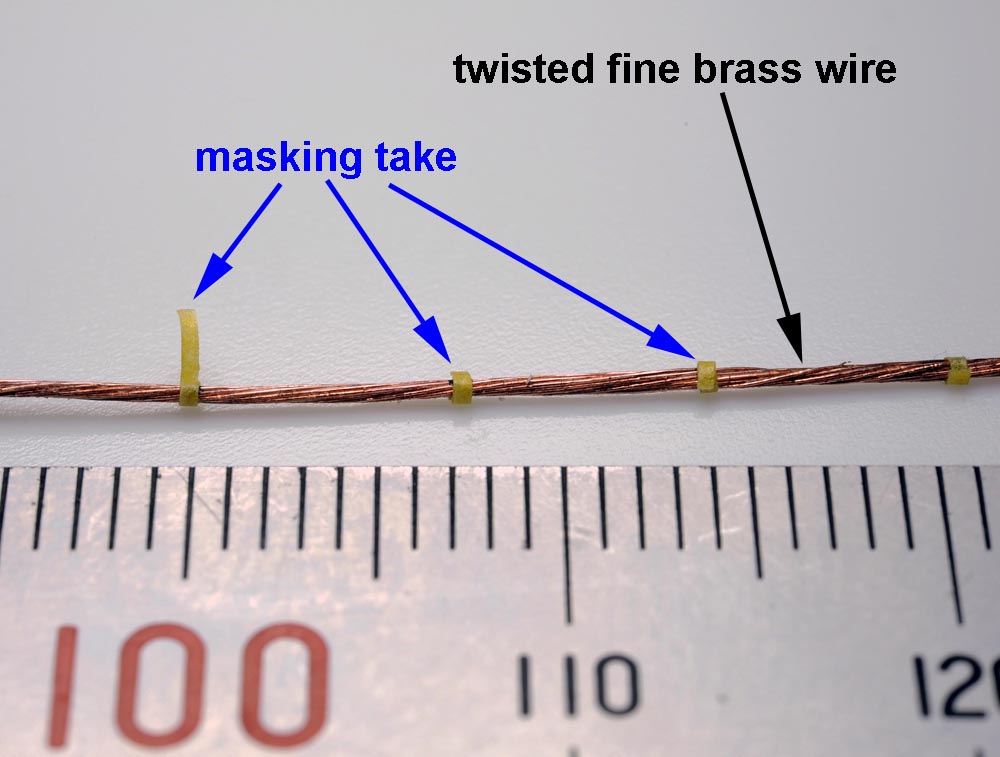
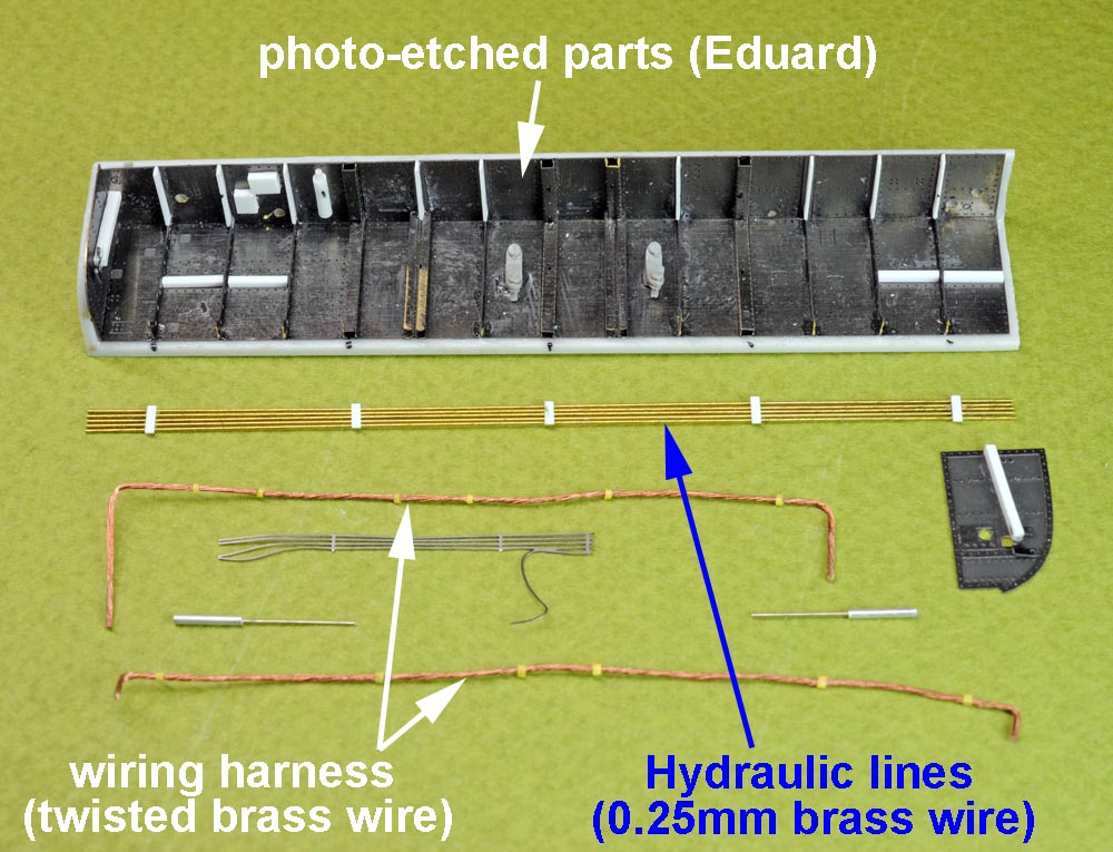
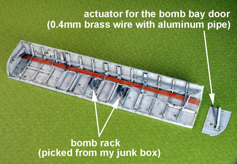
(above 2 photos),
A photo at left shows how I made "wiring harness" by using fine brass wire and a masking tape.
I twisted a bundle of fine brass wire and bundled it with masking tape at regular interval.
A photo at above right shows all the component parts to be assembled to the bomb bay, including Edward photo-etched parts and the brass wire.
【上2枚】、
左上の写真は爆弾槽内に這い回る組み電線(wiring harness) の作り方を示しています。
十数本の細い銅線をこよって、所々を細く切ったマスキングテープで束ねました。
右上の写真は爆弾槽内部の作り込みに使った構成部品を並べたものです。
槽内の壁はエッチング部品を貼込ました。槽内の配線や配管は主に真鍮や銅線で作りました。
爆弾槽扉の開閉用アクチュエーターは洋白線をアルミパイプに嵌め込みました。
.
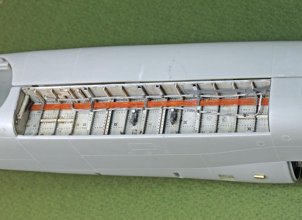
(above 4 photos),
After assembling the bomb bay, I painted it in white mostly and I washed it in brownish-black by using "Mr.Weathering Color-Ground Brown".
I started using this "Mr.Weathering Color"(by GSI Creos) soon after it was put on sale a few years ago and it works very good.
I can strongly recommend you to try to use it at least once.
The kit's bomb bay looks too shallow but I did not change it, because "changing it" should be a time-consuming heavy surgery.
【上4枚】、
爆弾槽内の組み立ての後、塗装(ほとんど白)を行い、更にクレオスの"Mr.Weathering Color-Ground Brown"で墨入れと汚れ表現を加えました。
発売以来この"Mr.Weathering Color"を愛用していますが、なかなか気に入っています。キャップに筆を付けてもらうと有難いんですがね。
キットの爆弾槽は実機に比べて浅すぎるようですが、これを深くする修正工事は他部品との干渉もあり、かなり大掛かりな外科手術となるので、そのままとしました。
槽内中央に2つの爆弾架を取り付けました。
.

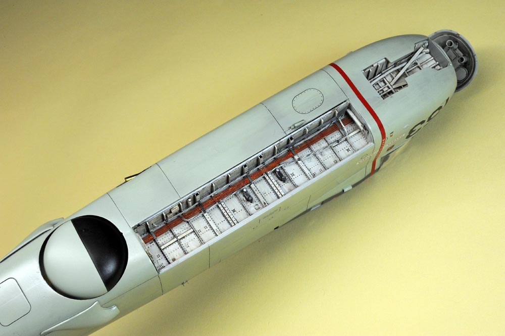
(above photo),
I realized that the left door (the outboard edge) of the bomb bay was slightly warped when I closely checked the above photo.
But, the bomb bay still looks generally OK and I'm fairly satisfied with the results of the bomb bay.
【上写真】、
この角度で写真を撮って初めて気付いたのですが、爆弾槽の左扉端面が外側に湾曲していますね。
でもまあ地上姿勢ではほとんど気にならない程度なので、このままにしておきます。
槽内が浅すぎるのも承知で作ってきましたが、それでも爆弾槽の仕上がりにはそれなりに満足しています。
.
Engine エンジン
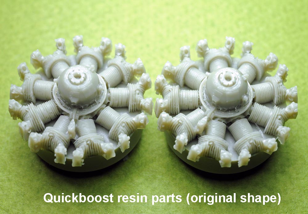
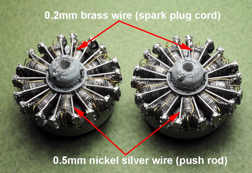
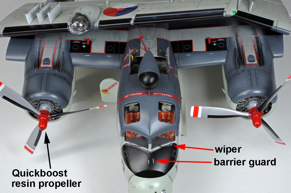
(above 2 photos),
I used the Quickboost's resin parts (QB48512) for the engine.
I only added the pushrods (0.5mm nickel silver wire) and plug cables (0.2mm brass wire) as shown on the above photo.
【上2枚】、
エンジンはクイックブーストのレジン部品に置き換えました。
同社の平均的なモールド品質より劣る製品のように思いました(上左写真)。
それでも、プッシュロッド(0.5mm洋白線)とプラグケーブル(0.2mm真鍮線)を追加すれば、なかなか見栄えが良くなりました(上右写真)。
.
Engine Nacelle ナセルの後部

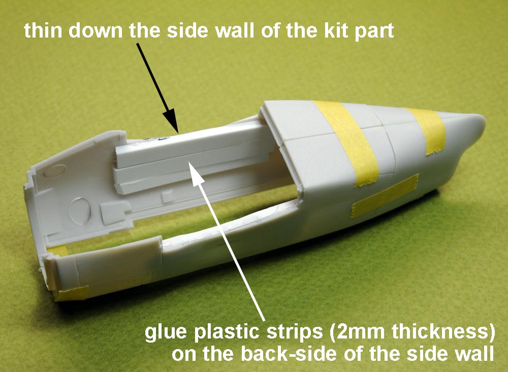
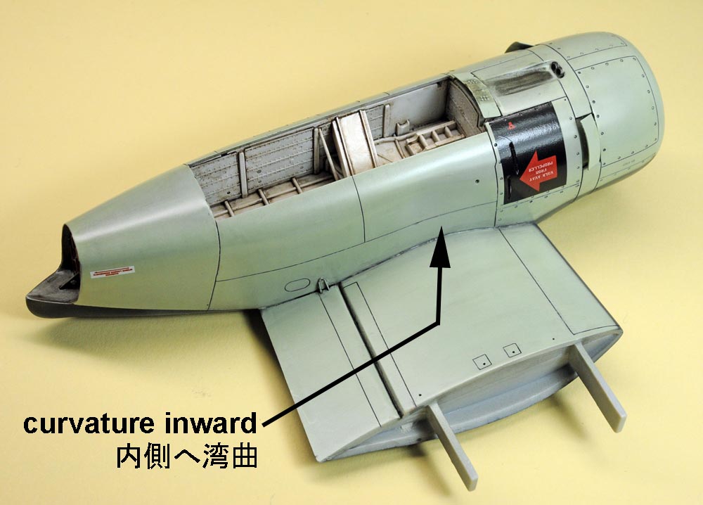
(above 4 photos),
A photo at top left shows the original shape of the kit parts, which is totally different from the actual S2F shape.
To change to shape of the side walls, I glued plastic strips (2mm thickness) on the back-side of the wall at first.
Then, I thinned down the side wall to make it hollow as shown on the photos at top-right & bottom-left.
【上4枚】、
エンジンナセル中央部の縦壁部は内側に湾曲しているのがトラッカーの外形的特徴の一つですが、キット部品(上左写真)では全く湾曲していません。
そこで、面倒臭いですが、ここだけはそれなりに修正することにしました。
まずは縦壁の裏面に2ミリ厚の樹脂板を貼り付けて、表面側から湾曲状に削り込みました。
一番深く削り込んだ場所では、キット部品の肉厚がほとんどゼロになりました。
.
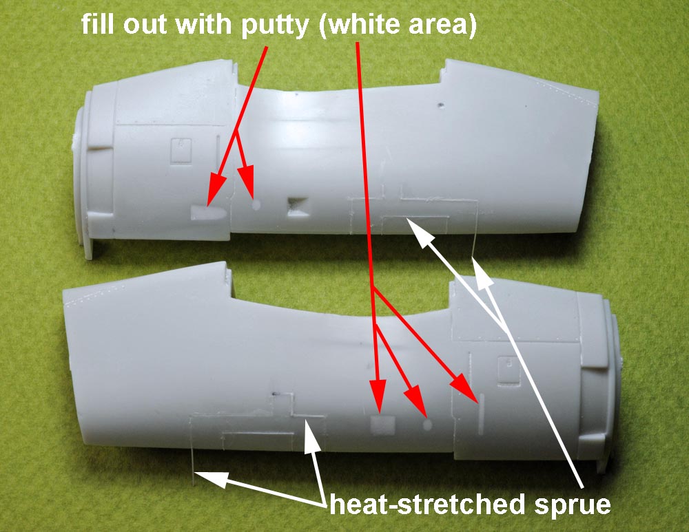
(above 2 photos),
Kit mold fully ignores surface details of the real airplane, so I glued heat-stretched sprue in the panel line and
I sanded over the surface to erase the original panel line.
I also filled up all the questionable dents(mold) with putty to erase them as shown on the photo at above left.
Then I newly scribed surface details based on the walk-around photos I took at museums.
【上2枚】、
ナセル中央部の表面モールド(パネルラインや凹み)は全く実機を無視しており、それらの修正にも面倒な工作を強いられました。
調査不足が主な原因と思われますが、無理なバリエーション展開も一因かと思います。
不要なパネルラインは伸ばしランナーを埋めて消し、訳のわからぬ凹みはパテで埋めました(左上写真)
左と右のエンジンナセルで、内面と外面とで夫々パネルライン等が相違しており、作っていて混乱しそうになりました。
.


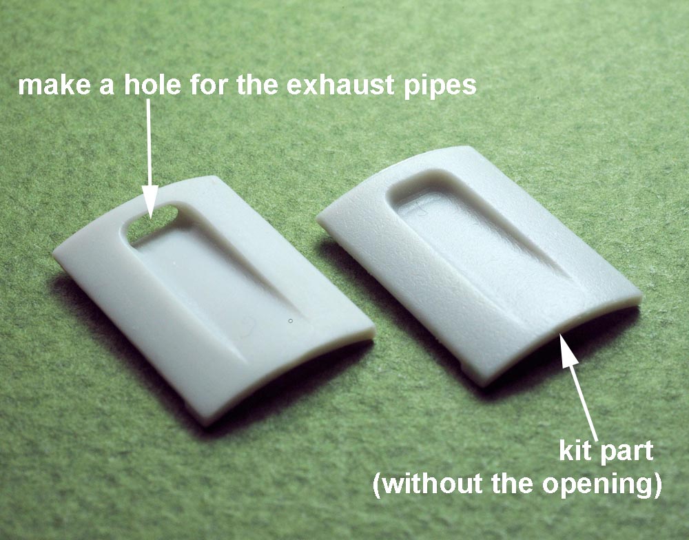

(above 4 photos),
The kit does not carry parts for the exhaust pipes.
So, I made holes for the exhaust openings (see photos top-left & bottom-left), and I used brass pipe for the exhaust pipe.
A photo at top right also shows a brass part (0.1mm thickness) near the exhaust pipe, which replaced a thick kit part.
【上4枚】、
本キットでは排気管が全く無視されているため、排気管が外に出る開口部をまず開けました(上左と下左の写真)。
そこに真鍮パイプを2本づつ短く切って接着しています(上右と下右の写真)。
右上の写真では、キット部品の代わりに使ったO.1ミリ厚の真鍮板(排気管の直ぐ脇)と、主翼上面の突起部品(キット部品の付け替え)も写り込んでいます。
.

(above 2 photos),
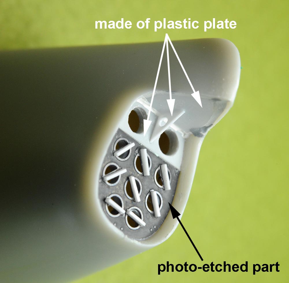
I used photo-etched parts for the sonobuoy dispenser as shown on the photo at above left.
I used plastic plate to build upper half of the rear end as shown on the photo at above right.
【上2枚】、
ナセル後部のソノブイ収納部は、左上の写真の如く、エッチング部品と樹脂の小片で作りました。
またその上部は、右上の写真の如く、実機写真を参考にしながら樹脂板で形作りました。
.
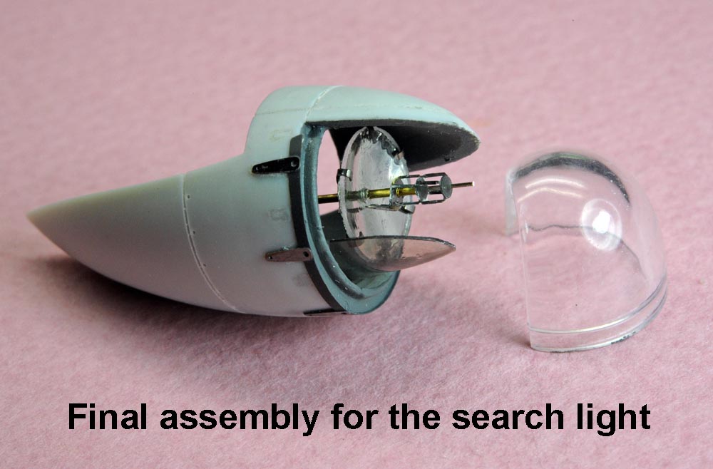
Search Light 探照灯
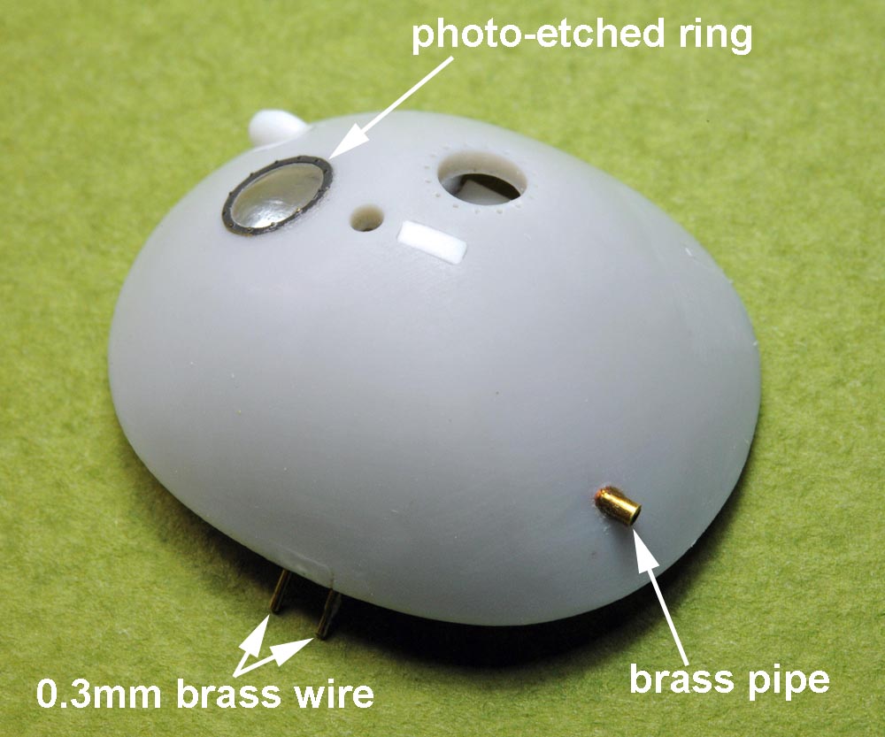
(above 3 photos),
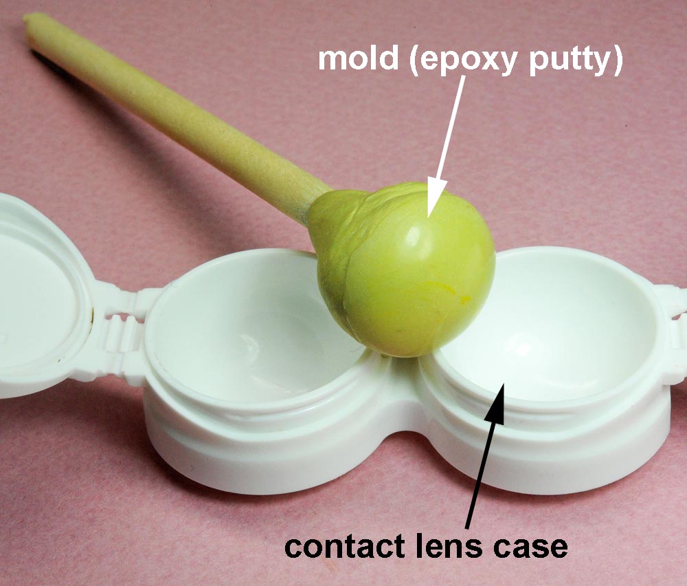
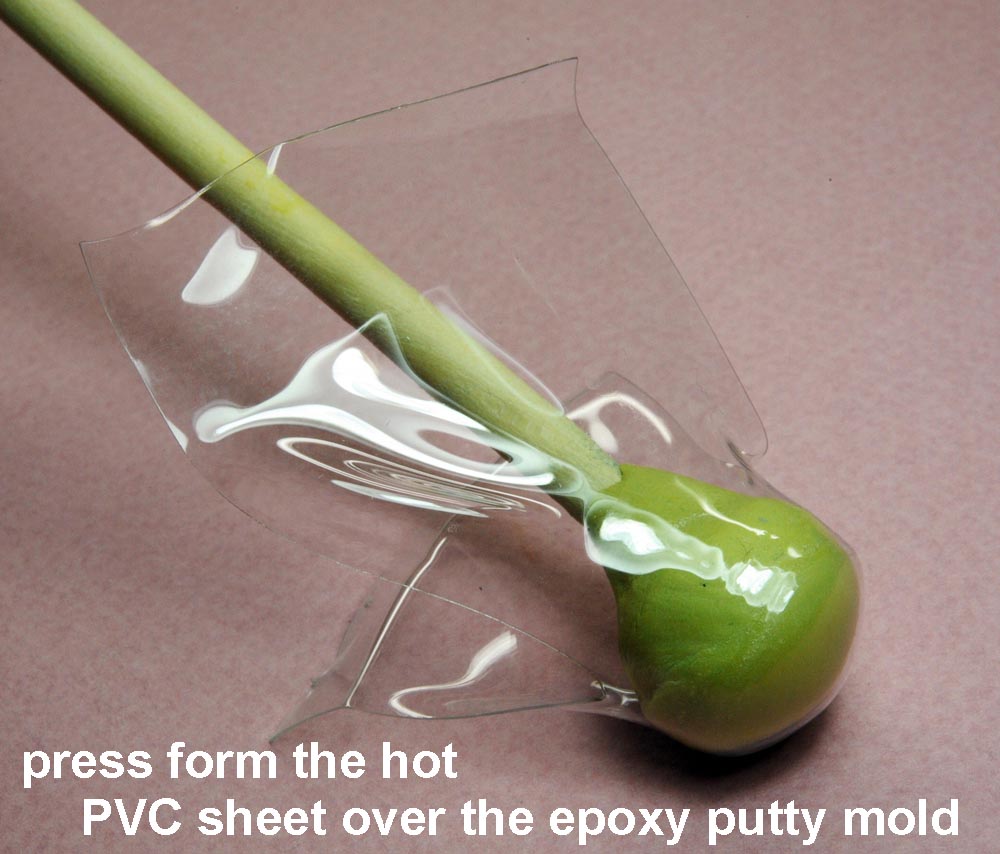
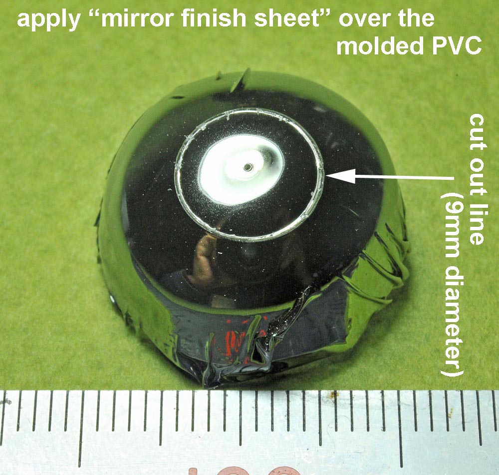
These photos show how I made the reflector for the search light.
At first, I made a hemisphere-shaped mold by using epoxy putty (see photo at above left).
Then, I formed a hemisphere-shaped PVC sheet by heat press process (see photo at above center).
Then, I applied "Mirror Finish" sheet over the outer serface of the hemisphere.
The reflector (9mm diameter) can be cut out from the hemisphere-shaped mirror sheet (see photo at above right)
【上3枚】、
これらの写真は小生が探照灯の反射板を作ったプロセスを撮ったものです。
まずエポキシパテで半球状の型を作り(上左写真)、それを使って塩ビ・シートを絞り出しました(上中央写真)。
その外表面にミラーフィニッシュを貼ってから、直径9ミリの円形を切り取って(上右写真)反射板としました。
しかし、次回からは薄いアルミ板を半球状に成形して反射板を作った方が、見栄えも良いし加工が容易になると思います。
.
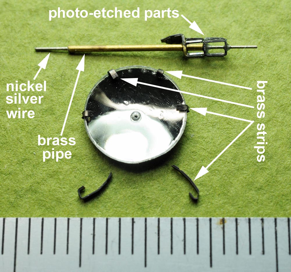
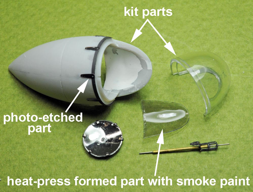
(above 4 photos), Six arms placed around the reflector are mede of small strips of brass,
and I made the light-emitting portion by using photo-etched parts and metal pipe/wire as shown on the photo at above left.
A photo at above right shows all the component parts I prepared for searchlight assembly.
【上4枚】、
反射板の周囲6箇所の固定アームは、左上の写真の如く、真鍮の小片を裏面から接着しました。
発光部はエッチング部品と金属線とパイプを組合せて、それなりに作りました。
右上の写真は探照灯内部の構成部品を並べたものです。
発光部の下側を覆っている透明部品は、絞り出しで作った塩ビ成形品にスモークをかけました。
.
Radome レドーム

(above 4 photos),
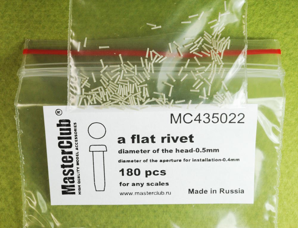
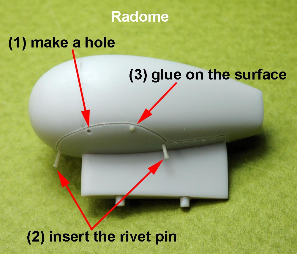
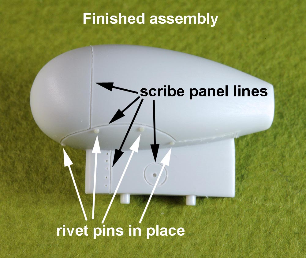
I recently purchased Master Club's resin rivet (see photo at top left) to be used for my next helicopter(Wessex) project.
So, I made a trial use of this resin rivet for my Tracker project in advance.
I noticed several screw heads(?) on the lower surface of the radome, and I used the resin rivet here.
I made a hole at first and inserted the rivet pin (resin) into the hole, and I glued it at last as shown on the photo at botton left.
I believe this is very useful item for my future helicopter project.
【上4枚】、
次作のWessexに使うため、Master Clubのレジン・リベットを購入してみました(左上写真)。
これを前もって試験的にトラッカーで使ってみようと思い、レドームの下にある凸部(ネジの頭?)にこのレジン・リベットを使ってみました。
穴を開けてこのリベットを植え込む訳ですが、少数本であれば簡単にすぐできます。
頭の形状や大きさは種々発売されていますが、購入費用を考えれば、将来は他の安価な方法で凸リベットを作ろうと思います。
.
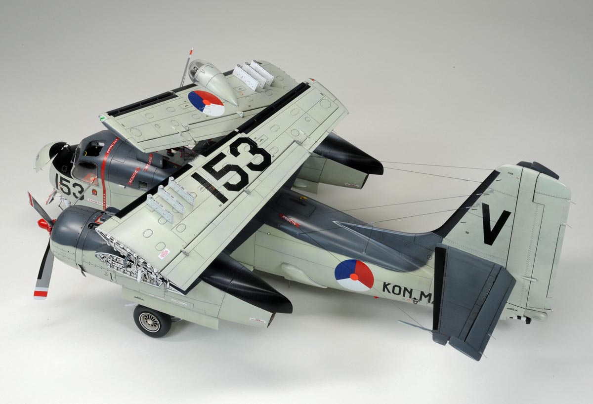
Wing Fold Mechanism 翼折畳み部
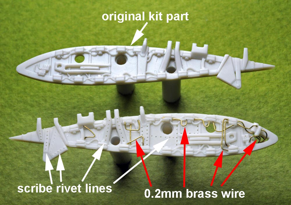
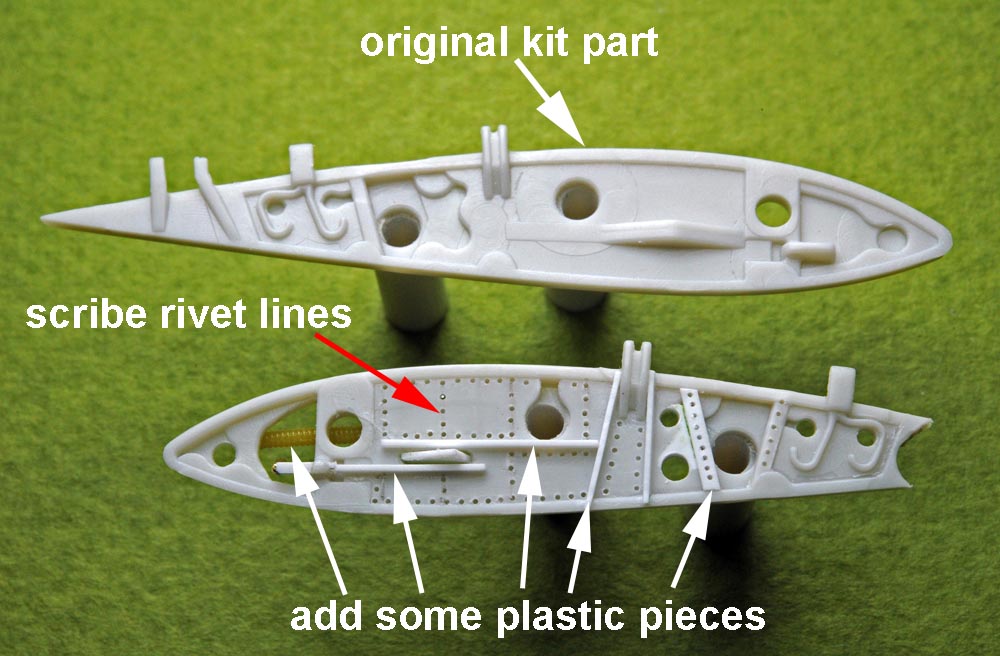
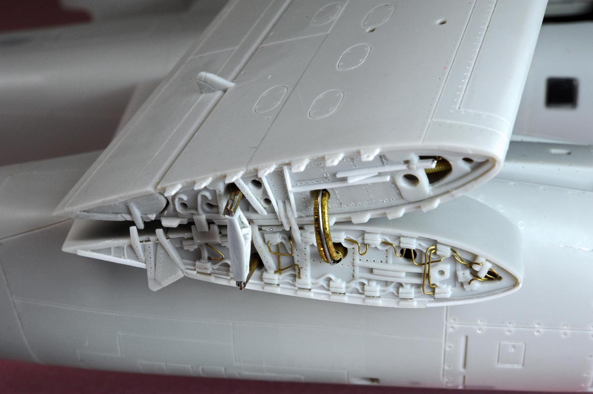
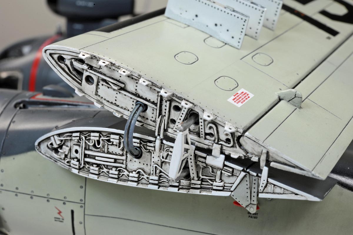
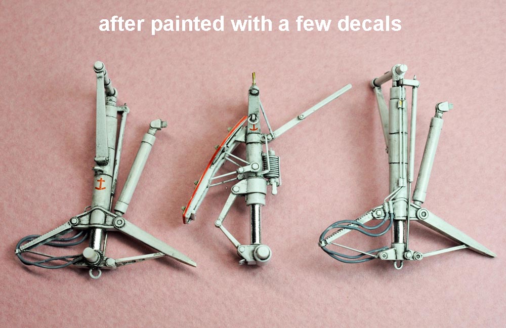
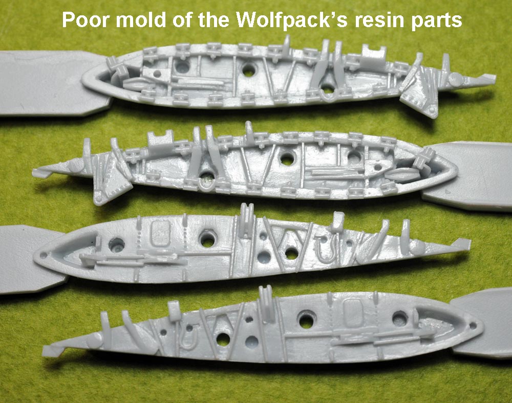 (above/left 3 photos),
I purchased Wolfpack's resin parts for the wing fold mechanism (see photo at bottom left), but I did NOT use it simply because the quality of the resin mold was so poor.
So, I added a lot of small details on the kit parts as shown on the photos at above left/right.
I used 0.2mm brass wire and plastic strips to add details together with scribing lots of rivet lines.
(above/left 3 photos),
I purchased Wolfpack's resin parts for the wing fold mechanism (see photo at bottom left), but I did NOT use it simply because the quality of the resin mold was so poor.
So, I added a lot of small details on the kit parts as shown on the photos at above left/right.
I used 0.2mm brass wire and plastic strips to add details together with scribing lots of rivet lines.
【上3枚】、
翼の折畳み部はこのモデルの見せ場の一つなので、Wolfpackのレジン部品を購入してみました(下左写真)。
しかし現品を見てビックリです。キットの部品よりもモールドが悪かったのです。
そこで、上段2枚の写真の如く、キット部品に細部を作り込んで使うことにしました。
複雑な油圧配管はこの部位のキモなので、0.2mmの真鍮線で配管を沢山追加しました。
又、樹脂棒やリベットの彫り込みなどで、ディテールを作り込みました。
.
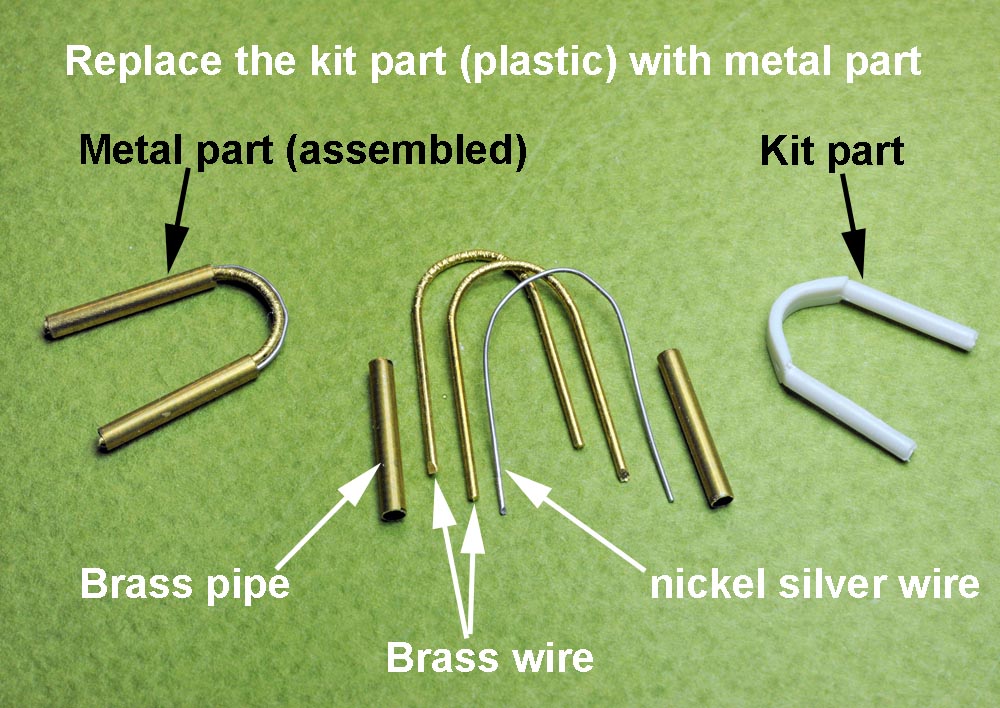
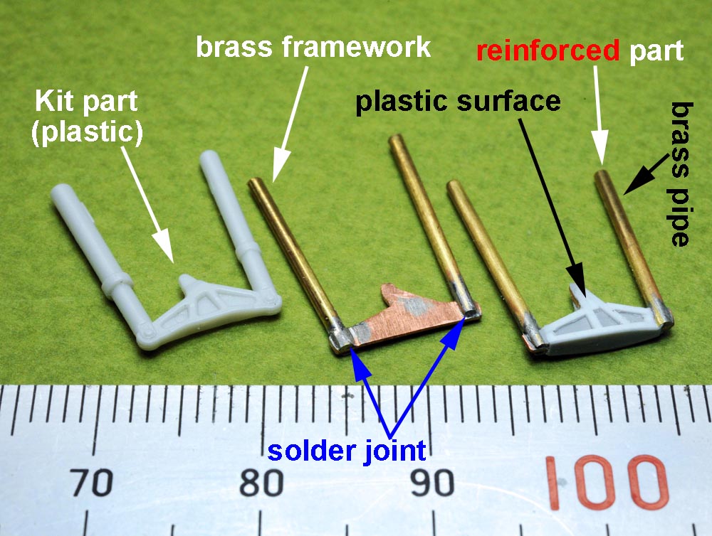
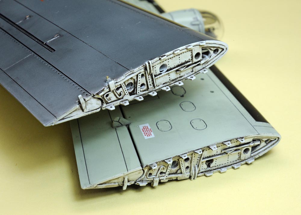
(above 2 photos),
As shown on the above two photos,
I replaced the wing joint parts (two pieces each side) with hand-made brass parts in order to reinforce the structure of the folded wings.
As you can imagine, it was time-consuming work with lots of test fits.
【上2枚】、
翼を折り畳んで完成させるには、内外翼を結合する左右2つづつの樹脂部品を金属に置き換える必要が有りました。
そこで、上2枚の写真の如く、主に真鍮の材料を加工して貧弱なキット部品を置き換えることにしました。
詳細は写真をご覧ください。
.
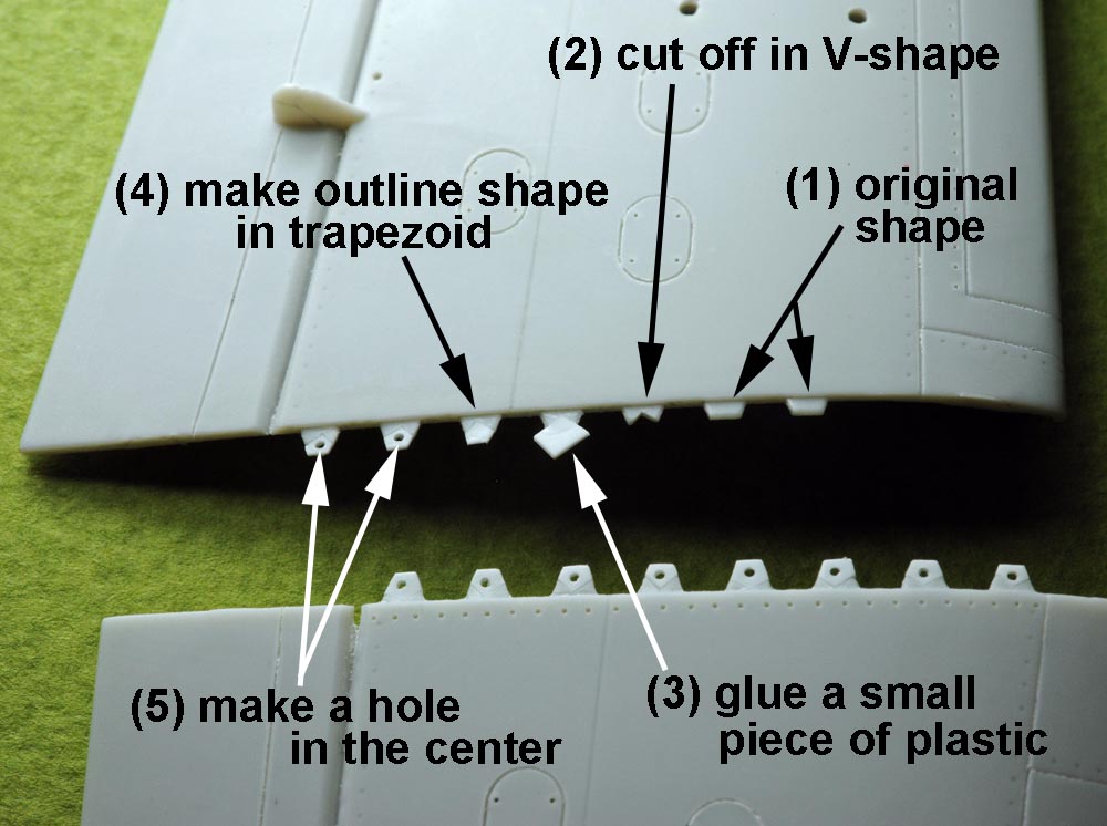
(above 2 photos),
A photo at above left shows how I made the trapezoid-shaped "latch plate(?)" in the realistic fashion.
On the kit part, the latch plate is too short to make a hole(for locking) in the center of the plate.
So, I glued a small plastic piece on top of the short plate to extend the length of the plate.
After the extension of the plate, I made a hole in the center.
This should be an important eye-catching point of the wing fold mechanism.
【上2枚】、
主翼折畳み部をちゃんと作ろうとすると、外翼下面に並んでいる差し込み用のベロ(?)を実機に近い形で作り直す必要が有ります。
その改造過程を左上の写真で説明しています。キット部品ではベロが短か過ぎて、その真ん中に穴(ロック棒を嵌め込む穴)が開けられません。
そこで、短か過ぎるベロの先端に樹脂片を継ぎ足して、ベロを延長します。その後に台形のベロの真ん中に穴を開ければ、実機に似た形を再現できました。
.
 BEFORE
painting
塗装前
 AFTER
AFTER
Painting
塗装後
Nose Landing Gear 前脚

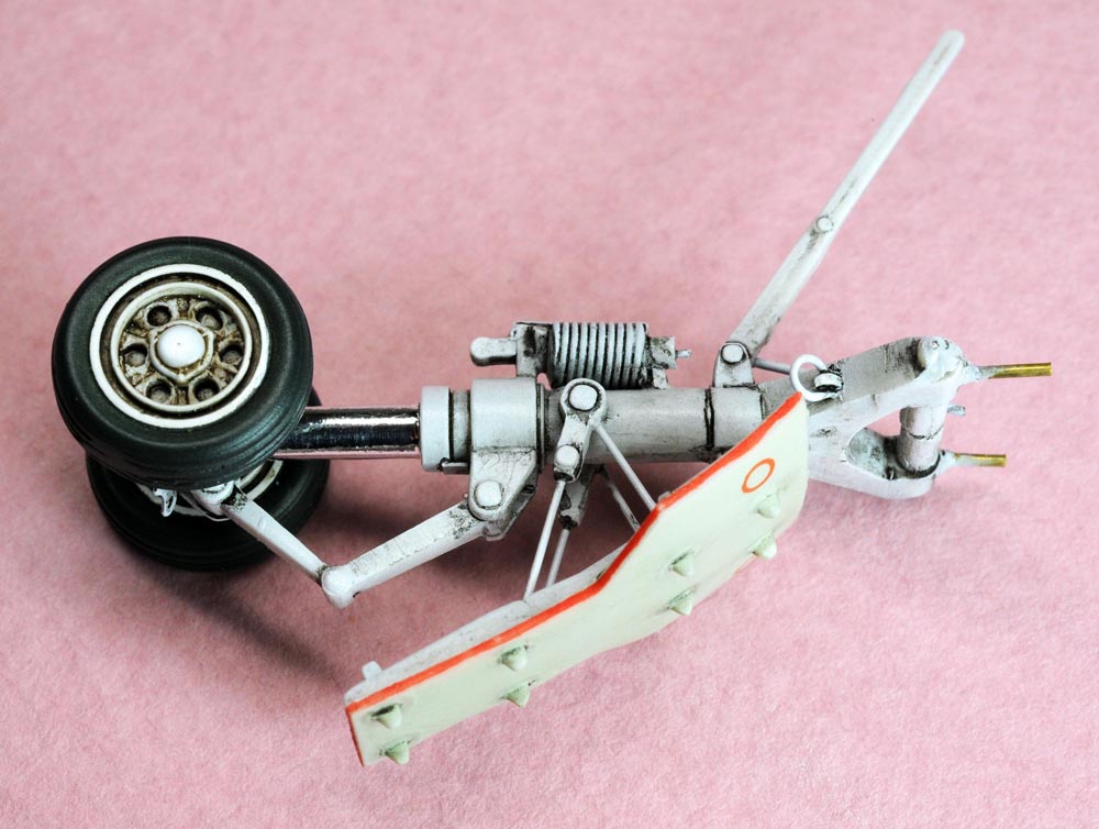
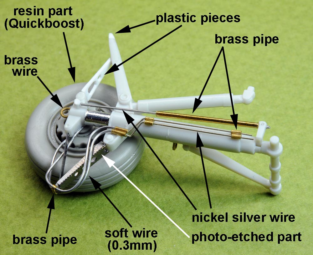
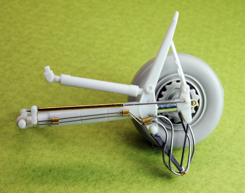
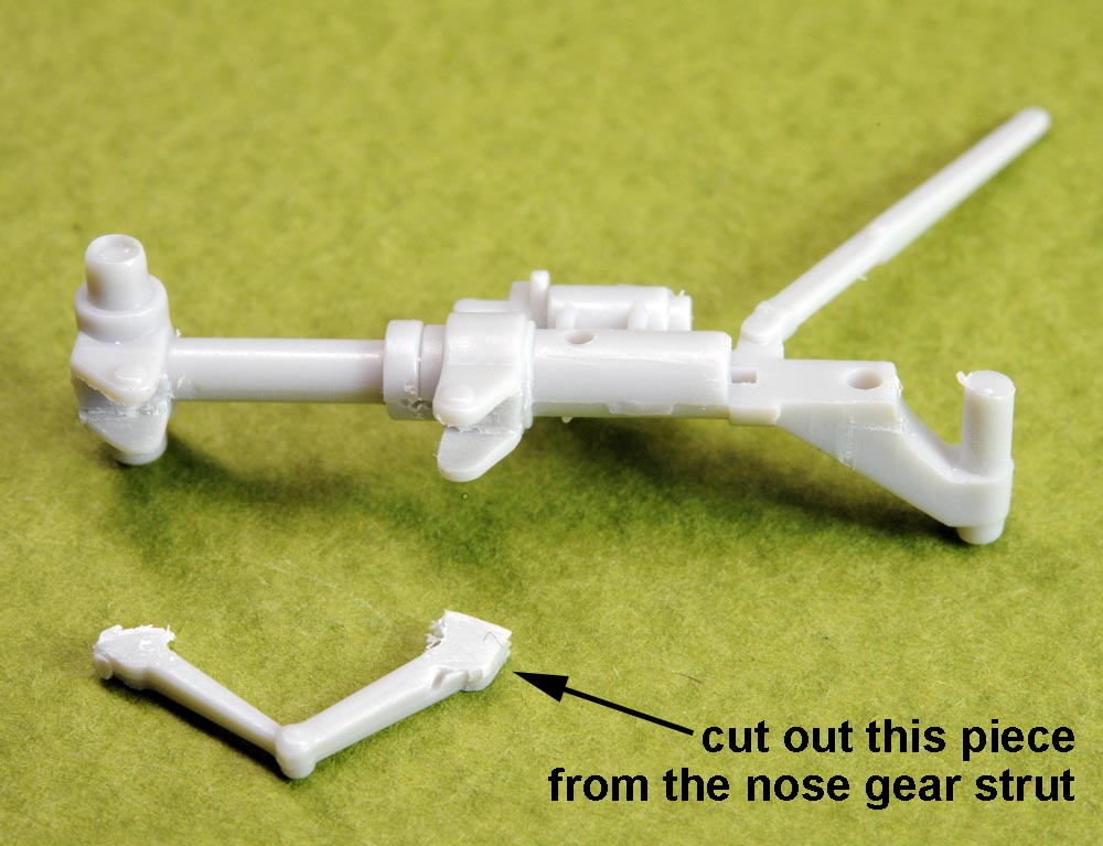 (above/left 3 photos),
I replaced some portions of the kit part (nose gear strut) with brass wire as shown on the photo at top left.
I applied the "mirror finish" sheet over the oleo to show the realistic effect.
Nose gear wheels are resin parts of Aires (Not of Quickboost as described on the photo at top left, Sorry!) .
(above/left 3 photos),
I replaced some portions of the kit part (nose gear strut) with brass wire as shown on the photo at top left.
I applied the "mirror finish" sheet over the oleo to show the realistic effect.
Nose gear wheels are resin parts of Aires (Not of Quickboost as described on the photo at top left, Sorry!) .
【上3枚】、
前脚は目立つ部位ですので、それなりに頑張りました。キット部品で太すぎる部分は真鍮線で作り直しました(上左写真)。
オレオの『く』の字アームは、脚柱から切り離して、別部品の感じ(?)を出しました(下段写真)。
車輪はアイリス(左上写真のQuickboost記述は間違いです。スミマセン!)のレジン部品を使いました。
前脚柱は2mmほど長過ぎるように思えたので、収納庫への取り付けを1.5mmほど深めに接着しました。
.
Main Landing Gear 主脚
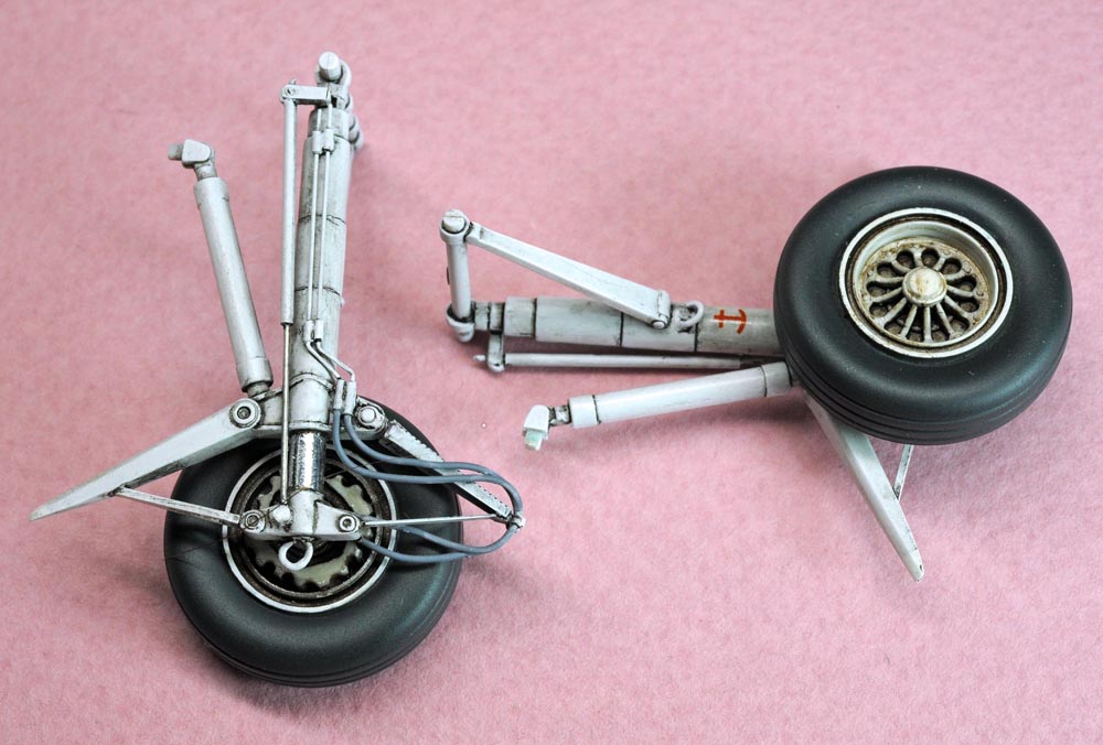
(above 4 photos),
I added some details as shown on the photo at top left by using various materials including brass wire/pipe and photo-etched parts.
Main gear wheels are resin parts of Aires (Not of Quickboost as described on the photo at top left, Sorry!) .
【上4枚】、
主脚も前脚に負けず劣らず頑張りました。前脚と同様に真鍮パイプや洋白線などを使って作り込んでいます(上左写真を参照ください)。
車輪はアイリス(前脚写真と同じくQuickboost記述は間違いです。スミマセン!)のレジン部品を使いました。
.
Outboard Wing 外翼

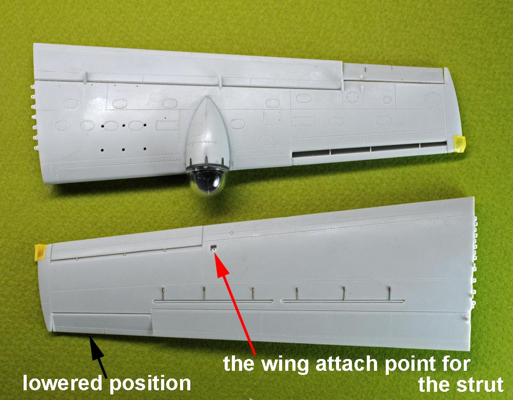
(above 2 photos),
Kit mold of the spoiler in stowed position is so poor, so I reworked it by adding some brass bits as shown on the photo at above left.
I also scribed heavy recessed line around the spoiler in stowed position.
A square dent was made for the attach point of the wing support strut on upper surface of the outboard wing (see photo at above right).
An aileron was separated from the wing and I placed it in the position off from the nutral.
【上2枚】、
外翼上面ににあるスポイラーのモールドはヒドイですねえ(上左写真の左側)。意味不明の溝と不可解な出っ張りがモールドされています。
型を設計した人はこれが何だか全くわからずに作ったんでしょう。
そこには真鍮の小片(作動アームのつもり)を埋め込み、併せてスポイラー板の外周を深く彫り込みました(左上写真を参照下さい)。
外翼を折り畳んだ時に外翼を支える支柱を嵌め込む支持ポイントを彫り込みました(右上写真)。
エルロンは切り離して、中立位置から少しズラして固定しました。
.
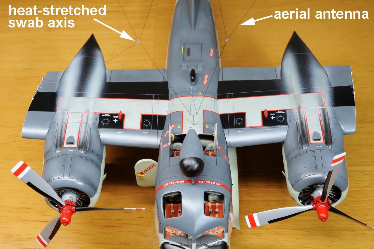
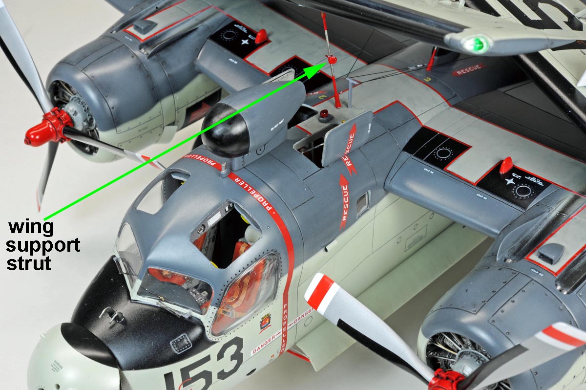
Aerial Antenna 空中線アンテナ
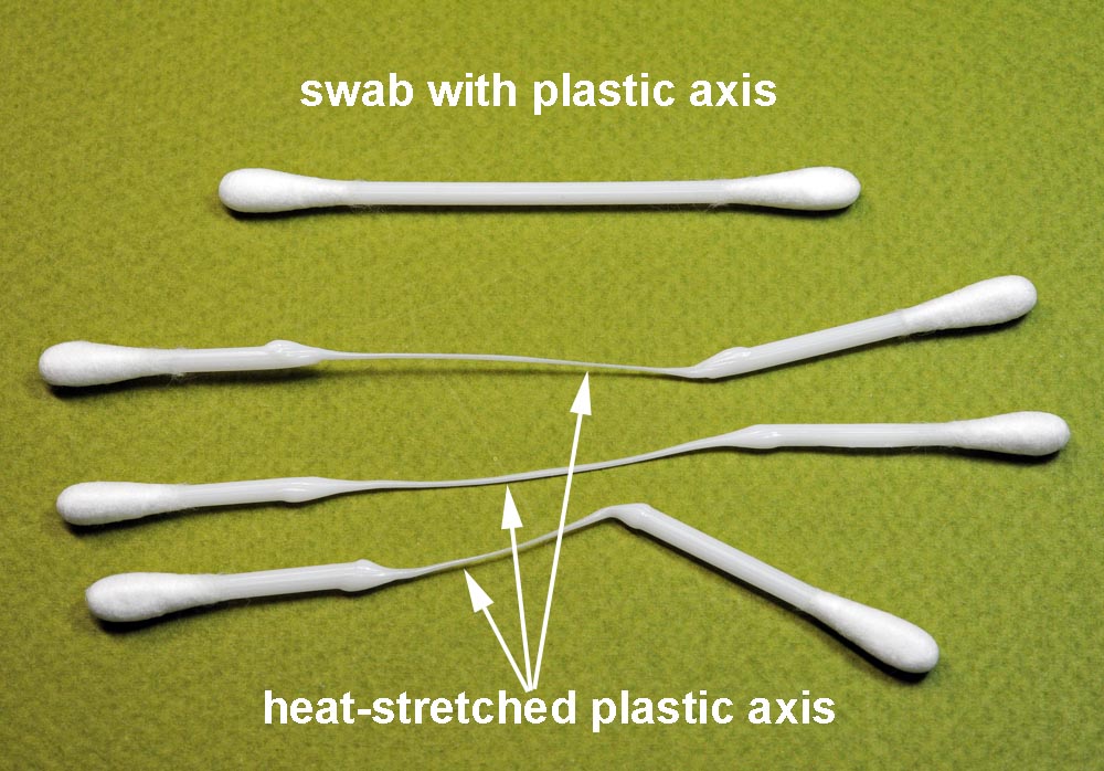
 (above/left 3 photos),
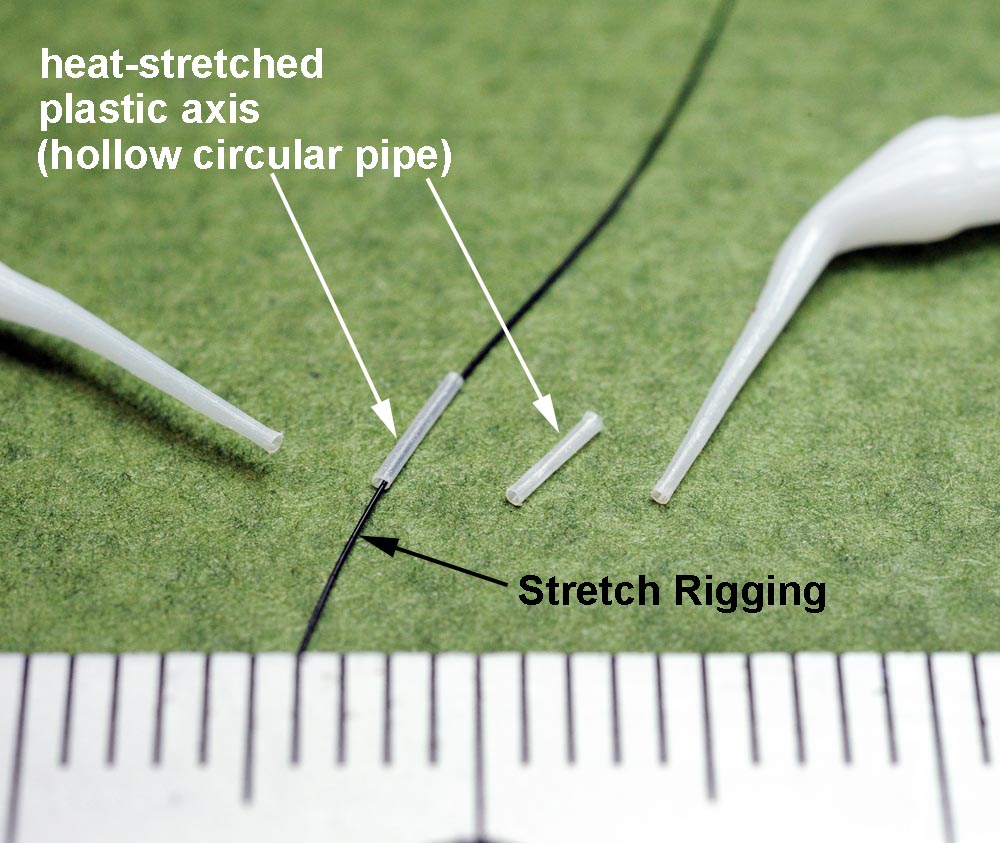
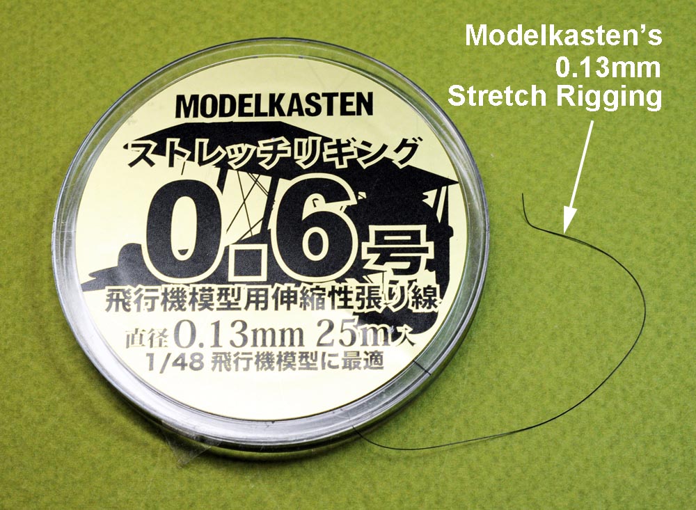
I used Modelkasten's "Stretch Rigging" (see photo at bottom left) for aerial antenna.
This material is stretchable by appox.10-15% and so, you don't need to care so much about the exact length of the antenna line when you cut it for assembly.
I used plastic axis of the swabs for insulators applied on the aerial antenna as shown on the photos at top left & right.
You can stretch the axis by using candle flame and you can make a fine plastic pipe in this process.
Then you can string the antenna line (stretch rigging) with the fine plastic pipe mentioned above as shown on the photo at top right.
(above/left 3 photos),
I used Modelkasten's "Stretch Rigging" (see photo at bottom left) for aerial antenna.
This material is stretchable by appox.10-15% and so, you don't need to care so much about the exact length of the antenna line when you cut it for assembly.
I used plastic axis of the swabs for insulators applied on the aerial antenna as shown on the photos at top left & right.
You can stretch the axis by using candle flame and you can make a fine plastic pipe in this process.
Then you can string the antenna line (stretch rigging) with the fine plastic pipe mentioned above as shown on the photo at top right.
【上3枚】、
これら写真はいずれもプラモ仲間の先輩達から教えていただいたアイテム(方法)です。
まず空中線アンテナですが、モデルカステンのストレッチリギングを使いました(左下写真)。
10〜15%程度伸ばすことが出来るので、機体に取付けるのがとても楽になりました。
次はアンテナ線に取り付けられている円筒状の部品(碍子など?)ですが、ここには今回初めて『伸ばし綿棒』を使ってみました(左上と右上写真)。
従来は真鍮パイプを使っていましたが、『伸ばし綿棒』の方が工作が容易と思いました。
しかもこの『伸ばし綿棒』は飛行機プラモの細部作り込みに色々な使い道があると思います。
.

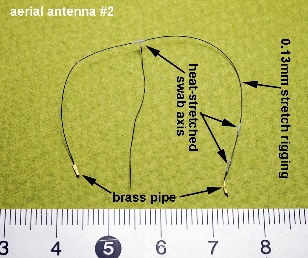
(above 2 photos),
I assembled two antenna systems #1(above left) and #2(above right).
I used a brass pipe for antenna strut placed on top of the mid-fuselage.
【上2枚】、
アンテナ空中線は2系統(左上と右上写真)に別けて作りました。
中央胴体の上に立てるアンテナ支柱(T字型)は真鍮パイプを潰しハンダ付けで作りました。
アンテナの端末留め(垂直/水平尾翼)にもアンテナ線を中に通して潰した真鍮パイプを使いました。
.
Main Gear Well 主脚庫


(above 2 photos),
These photos show how I added details in the main gear well and the engine nacelle surfaces.
I used some photo-etched parts for the detals.
【上2枚】、
主脚庫内はエッチング部品や樹脂材で作り込みました。エンジンナセル表面にもエッチング部品を使っています。
.
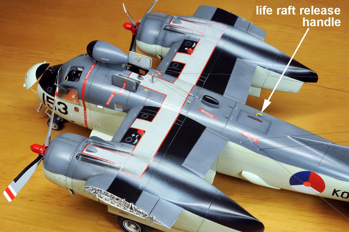
Others その他
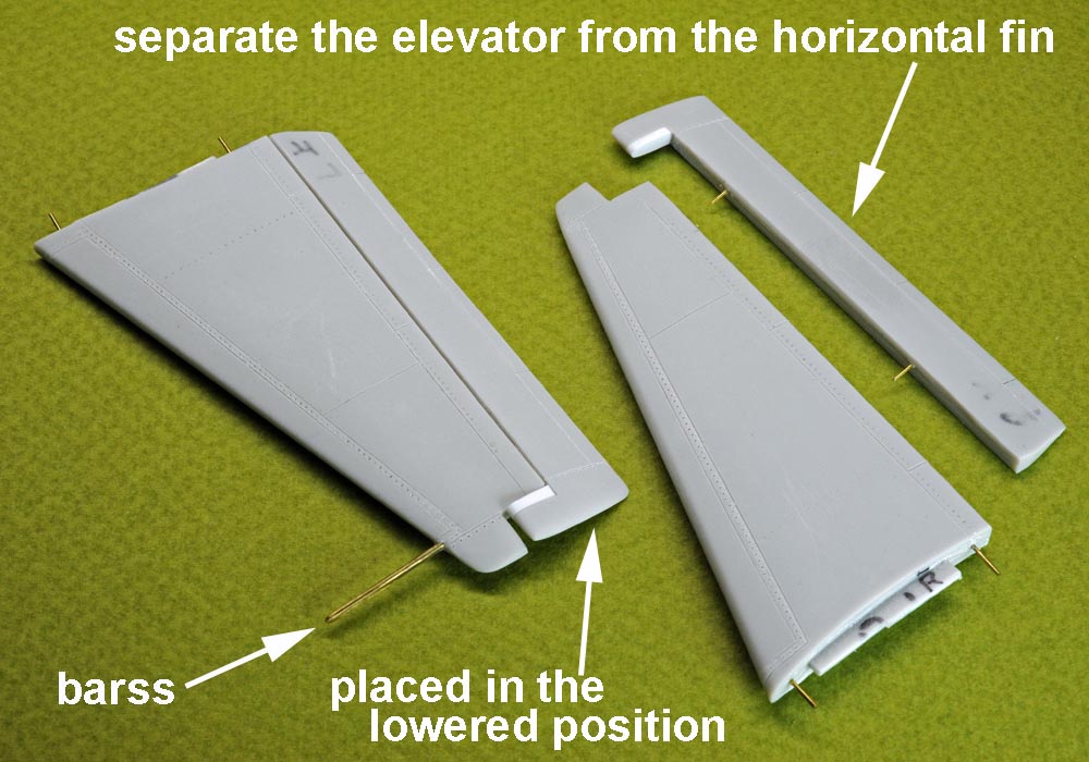

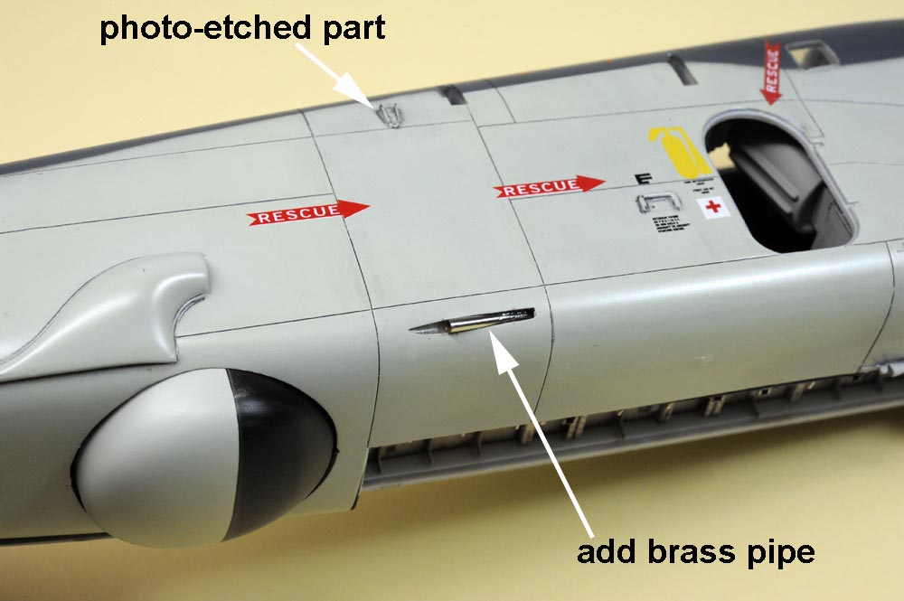
(above 4 photos),
"TOP LEFT", I separated the elevator portion and I glued it in the lowered position.
"TOP RIGHT", This photo shows small external parts including kit parts, resin parts and hand-made parts.
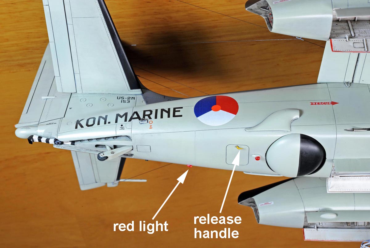
"BOTTOM LEFT", This kit completely ignors the outlet pipe pictured on this photo, so I added it with the brass pipe.
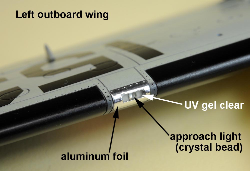
"BOTTOM RIGHT", I used a crystal bead for the approach light. I applied "UV Gel Clear" around the approach light and finally I applied an aluminum foil around it over the surface.
【上4枚】、
[上左]昇降舵は水平尾翼から一旦切り離し、少し下げ位置で取り付けました。動きが表現されて好きなんです。
[上右]機体表面に取付ける小物部品を並べてあります。あちこちに付いている黄色のL字ハンドルは真鍮棒を削って作りました。
[下左]キットでは中央胴体の右下面から突き出しているパイプが全く省略されていたため、真鍮パイプとそれを取付ける溝を追加しました。
[下右]左前縁にあるアプローチライトですが、ライト本体はビーズ屋さんで買ってきたピカピカの透明ビーズです。
その周りを"UV Gel Clear"で固めてから、表面(前縁部)にキッチンテープ(アルミ箔)を貼り付けました。
.
Progress of Process 製作の進捗
 (1)
(1)
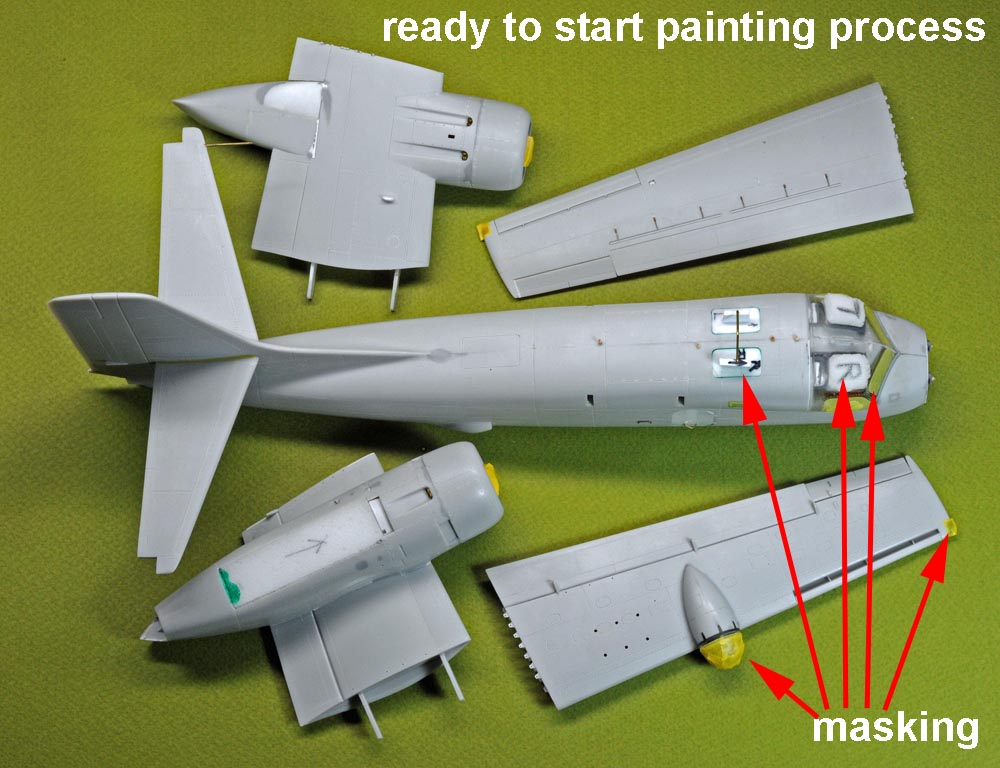
BEFORE START PAINTING
Masking process was already done.
【下塗りの開始直前】
マスキングは既に済ませています。
 (2)
(2)
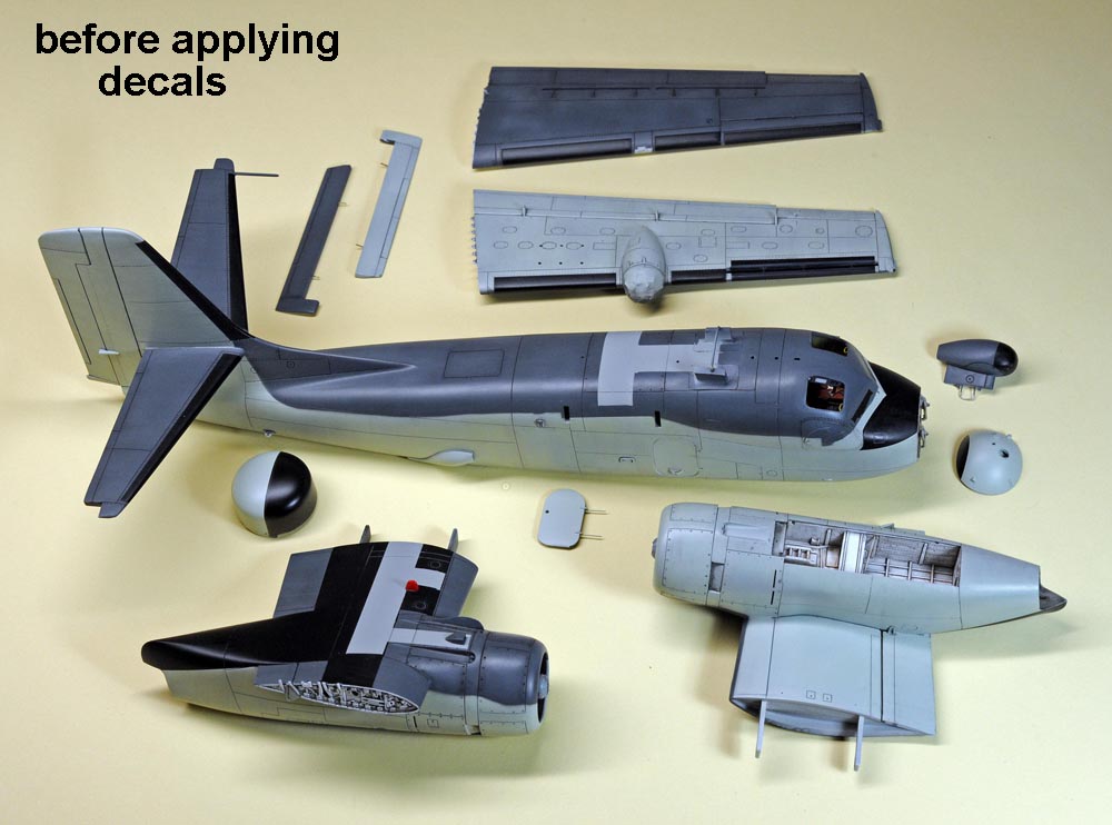
BEFORE APPLYING DECALS
Painting process was done already.
【デカール貼りの開始直前】デカール貼りの開始直前
基本塗装は既に済ませています。
 (3)
(3)
BEFORE MAJOR ASSEMBLY
Each majoy component(inboard/outboard wing and fuselage) was almost completed including clear top coat.
【翼と胴体の結合直前】
翼と胴体は個別にトップコート(半艶消しのクリアー)を既に吹いてあります。
 (4)
(4)
GLUE FUSELAGE & INBOARD WING TOGETHER
Fit between the fuselage and the inboard wing is very good, and I didn't use any putty at all.
After that, I glued the undercarriage, and then I put the aerial antennas in place over the fuselage and fin.
【翼と胴体の結合】
内翼と胴体の合わせは良好で、パテは一切使いませんでした。その後、前脚と主脚を取り付けて、最後にアンテナ空中線を胴体と尾翼の間に張りました。
 (5)
(5)
FINAL COMPLETION
Finally, I fixed the outboard wing over to the inboard wing.
【完成】
主翼の外翼部を内翼に取り付けて完成です。
UpperSurfaces of the Fuselage
胴体と内翼の上面


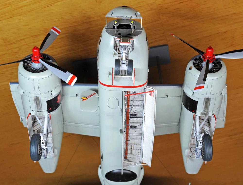
Under Surfaces of the a/c 機体下面
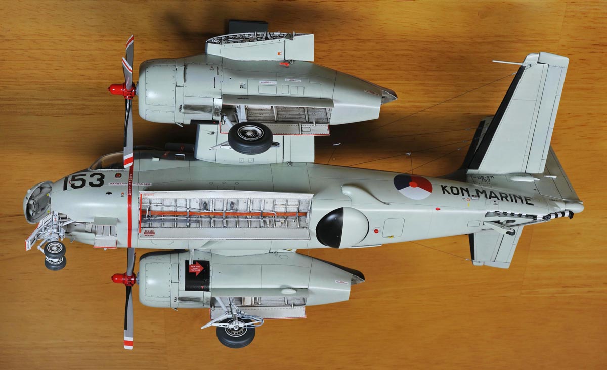

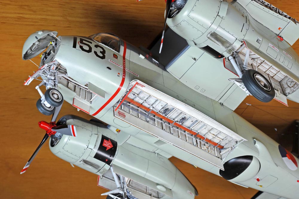
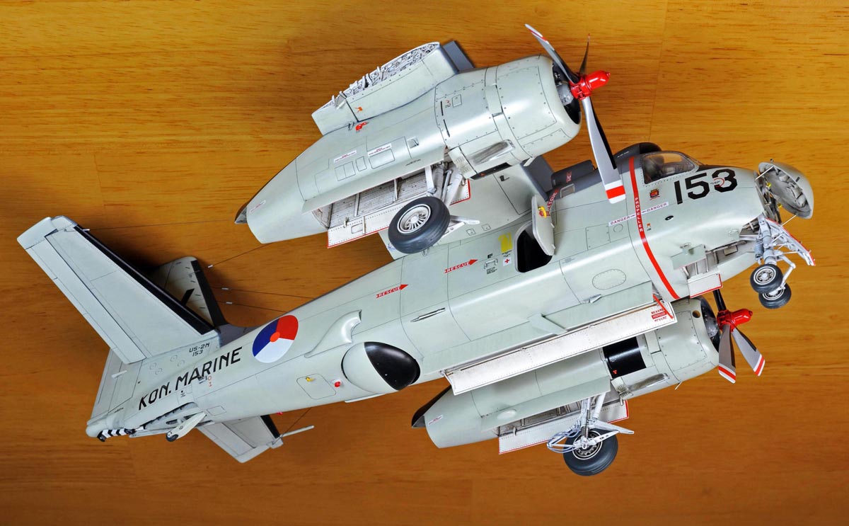
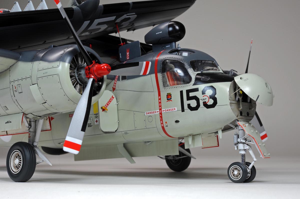
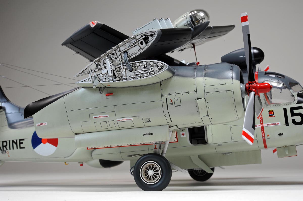
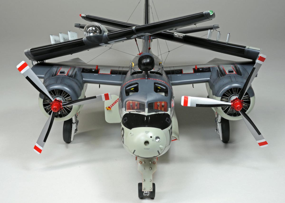
Final Completion 完成写真

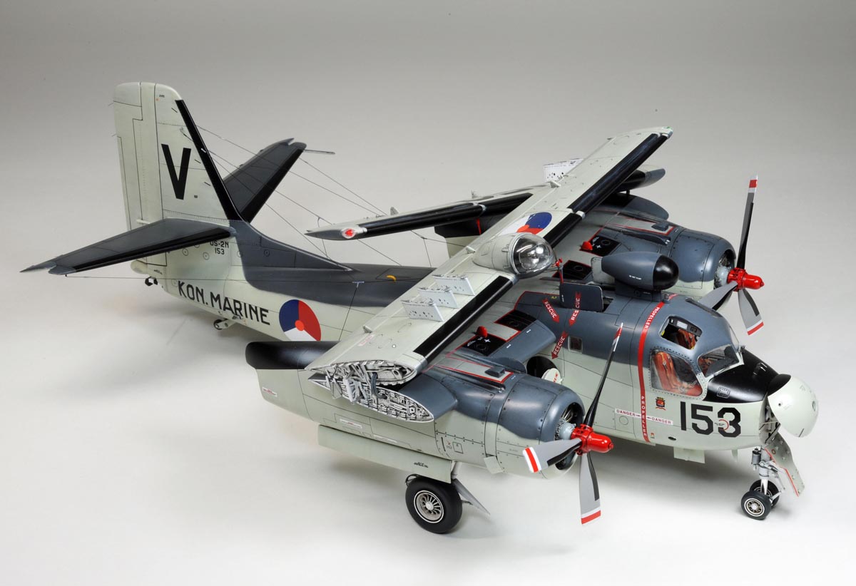

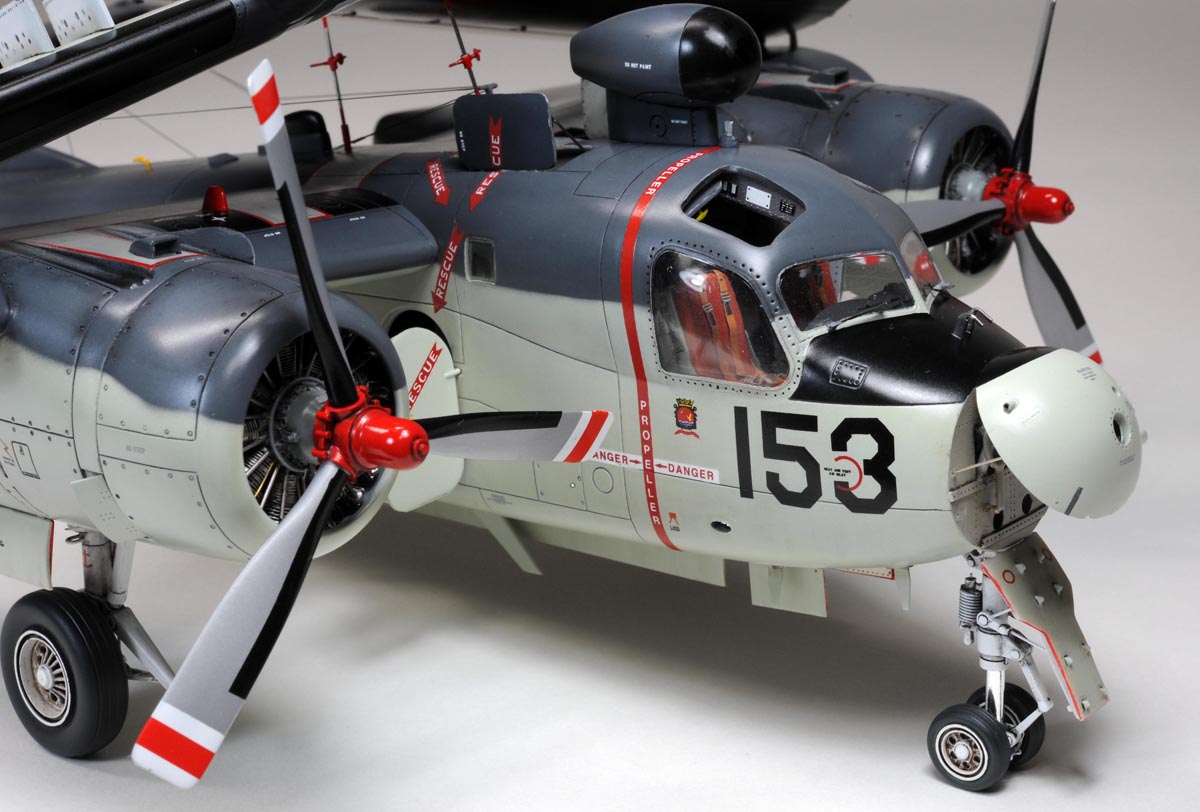
As a matter of fact, I made a detachable supporting rod (0.5mm piano wire) under the radome of the mid-fuselage in order not to sit the tail.
At the beginning, I planned to use the tail hook in lowered position to prevent the tail sitting.
However, I realized that the tail hook of the kit was not strong enough to support the tail.
That's why, I reluctantly had to use the supporting rod as mentioned above.
I'm sneaky enough to erase the 0.5mm piano wire under the radore from some of the photos by using a "photoshop" software. Sorry!!
上の写真の中には小生がインチキして画像処理を施した写真があります。
当初は尻もちをさせない為に、機首にオモリを詰め込もうとしたのですが、
胴体前部の内部を色々と作り込んでいく内にオモリを納めるスペースが取れなくなりました。
やむ無く着艦フックを下ろして尻もち防止を考えましたが、最後になってそれを試してみたら、フックがかなり曲がってしまうことが判明しました。
ここまで来たらもう万事休すデス。
下面のレドームの下に着脱式の『つっかえ棒』、実際は0.5mmのピアノ線を付けました。
完成写真はこのつっかえ棒が写り込まないように撮影角度を工夫しましたが、どうしても写り込んでしまうコマも少しありました。
これらのコマは画像処理でインチキし、フォトショップでつっかえ棒を消しています。
悪しからず。
.

Afterword あとがき
Frankly speaking, I cannot recommend you to build this kit if you closely care about the shape/comtour of the finished model,
because I'm not happy with the shape of various areas including the engine nacelle, the radome above cockpit and the searchlight fairing.
The most unhappy area is the poor shape of a part of engin nacelle where blending into the leading edge of the wing.
But still I enjoyed building this kit and I'm generally satisfied with the results of my Tracker.
このキットは典型的な中国製モデルの一つだと思います。
ちょっと見にはキレイなモールドが魅力的ですが、作り進んでいくごとに、アチコチに実機とは似つかない形状部位が現れてきて、イラつきます。
比較的容易な外科手術で修正できれば、ヤルしかないですが、修正不能な部位は自分を何とか納得させて諦めるしかありません。
一番気になった部位は、エンジンナセルが主翼前縁と交わる部分です。小生の技術ではとても修正出来ず、泣く泣く諦めました。
などと不満ばかり言っていては、老後のプラモ人生は楽しくありません。長生きするためには、キネティックさんにも感謝しなければなりません。
完成したトラッカーをしげしげと眺めながら、カッコいいなあ〜、やっぱオランダ海軍はいいなあ〜、って大満足に浸っている今日このごろです。