

I visited "East Midlands Aeropark" located in the north-west corner of East Midlands Airport in August 2014.
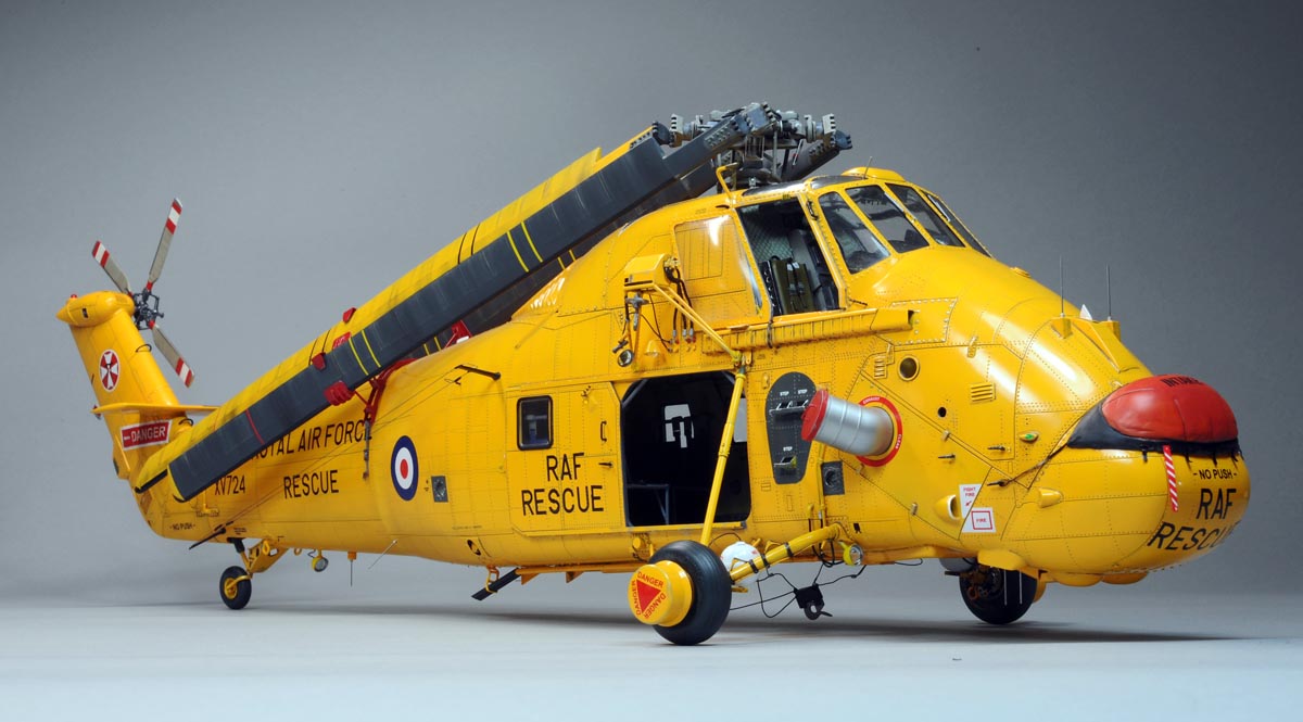
I took a lot of walk-around photos of several aircraft displayed at the Aeropark at that time including Westland Wessex HAR.2 (please see the photo at above left).
The cabin and the cockpit of the Wessex were accessible in the Aeropark and I was able to photograph cabin/cockpit details as well.
So, when the Wessex kit in 1/32 scale was released from FLY, I immediately decided to buy it, and I started building the kit in June 2016.
I used my Wessex photos taken at the Aeropark as main reference for my 1/32 Wessex.
Yellow paint scheme was so attractive to me, so the HAR.2 (RAF Rescue type) was the only choice of my Wessex project.
A lot of walk-around photos which I took in England in 2014 are shown on the walk-around section
of this website.....(click HERE) .
2014年7~8月に英国各地の博物館を訪問し、色々な Westland Wessex の細部写真を撮ってきました。
その写真の多くを、このHPの細部写真セクションに掲載しました『ココに掲載中』。
いつか1/48のWessexを作ろうと考えていた時に、FLYから1/32のデカいWessexが発売されるニュースを知りました。
これはタイミングが良いと、発売直後に早速購入し、2016年6月から製作を始めました。
Wessexには色々なバリエーションが有りますが、派手で目立つキレイなWessexを作りたいと思い、迷う事無くRAFの救難ヘリ"HAR.2"を作る事に決めました。
その裏には2014年に"East Midlands Aeropark"で"HAR.2"(左上写真)の細部写真を機内も含めて沢山撮れた事と、
所属クラブの年間テーマ機に救難機が含まれていた事も、"HAR.2"を選ぶ決め手になりました。
各部の塗装色を決める時や、細部作り込みの参考資料として"East Midlands Aeropark"で撮影した"HAR.2"の写真を主に使いました。
折角のキレイな機体表面には一切の汚しを施さないこと(退色表現は別)と、程良いツヤを出して黄色を輝かせる事を念頭に作りました。
You can enlarge all the photos on this page by clicking on images.
クリックで本ページ内の全ての画像を拡大出来ます
Cabin details キャビン製作


(above 4 photos),At first, I assembled the heater duct (to be mounted on the upper cabin wall)
and the blowoff port/duct (to be placed near the cabin floor).
I used thin(0.2mm) lead plates for the heat insulator wrapped around the duct(white plastic strip), as shown on the photos at top left and at top right.
I wrapped aluminum foil around the blowoff port of the heater system as shown on the photo at bottom left.
I drilled small holes on the aluminum foil as air outlet nozzles.
A photo at bottom right shows the heater duct (painted in orange) and the blowoff duct wrapped with the aluminum foil in its finished shape.
【上4枚】、キャビン内で目立つ装備品の一つが暖房用ダクトと床近くに設置された温風の吹出し口です。
キットでは無視されているので、ダクトは樹脂棒の周りに断熱材を模した鉛板を巻き付けて自作しました(上左と上右写真)。
温風の吹出し用ダクトは、実機では無塗装の銀であるため、樹脂棒にアルミ箔を貼り付けて、吹出しノズルに見立てた小さな穴を沢山空けました(左下写真)。
右下の写真は暖房装置の送風ダクト(上)と温風吹出しダクト(下)の完成状態です。


(above 4 photos) Accoring to the cabin photos of the RAF's Wessex HAR.2 in the rescue role, a large area of the walls and the floor were covered with waterploof sheet.
I used thin(0.2mm) lead plate as the waterploof sheet.
So, I glued the lead plates (with wrinkles) on the surfaces of the kit parts of the walls and floor as shown on the above photos.
I added a couple of cabin lights on the cabin ceiling as shown on the photo at bottom right.
【上4枚】、
英空軍の救難型Wessexのキャビン内写真を見ると、キャビン内の縦壁の大半と床面には防水シートが張られています。
それを表現するために、0.2ミリ厚の鉛板を使いました。実機の防水シートにはかなりシワがよっており、円形(ボタン状)のファスナーで壁に取り付けられています。
上4枚の写真は、それを作り込んでいる様子を表わしています。天井にはライトを2灯、前壁には消火器を取り付けました。
.


(above 2 photos)
I scratch-built containers (large bags) for various rescue equipment by using epoxy putty and a thin lead plate.
A photo at above left shows the containers/bags and rescue harnesses before painting.
A photo at above right shows the cabin seats which I assembled by using kit parts including paper seats, paper seat-belts, plastic frames and photo-etched buckles.
The feel of a texture(material) is poor on the paper seats, but I didn't care so much about it simply because the seats are not clearly visible after the Wessex model is finished.
【上2枚】、
現役時代の実機写真を見ると、キャビン内の左壁に沢山のバッグが掛けられています。
これらのバッグには色々な救難装具が収められているようです。
それらのバッグ類をエポキシパテ(バッグ本体)と薄い鉛板(フタ部分)で作りました(左上写真)。
キャビン内のシートはキットに入っていた部品のみを使って作りました。
シートの布部分とシートベルトは紙部品で、バックルはエッチング部品です。
紙部品では全く質感に乏しいですが、模型が完成すれば外からはほとんど見えなくなるので、気にせずそのまま使いました(右上写真)。
.


(above 4 photos),
The above four photos show how I assembled the details of the side walls of the cabin.
As for the left wall, I glued the heater duct and the blowoff port(duct) at first together with the wiring harnesses on the upper wall as shown on the photo at top left.
Then I glued a thin(0.2mm) lead plate over the wall and I glued a couple of white rectangular plastic plates(0.3mm) on the lead plate as shown on the photo at top right.
Then, I placed the hand-made bags(containers) on the rectangular plates as shown on the photo at bottom left.
A photo at bottom right shows a right cabin wall with a thin lead plate as a waterproof sheet.
【上4枚】、
上4枚の写真は、キャビン内左右の縦壁の組立てについて順番に示しています。
左壁については、まずワイアリングハーネス(真鍮線を束ねた)を壁上側に這わした後、
暖房用ダクト(オレンジ)と暖気吹出し口(アルミフォイル)を組み付けました(上左写真)。
その次に薄い鉛板を防水シートのつもりで壁面に貼り付けて、その上から0.3ミリの長方形の樹脂板を2枚貼り付けました(上右写真)。
更に、この樹脂板上に自作したバッグ類を実機写真を参考に配列しました(下左写真)。
右下の写真は右壁ですが、完成するとほとんど見えなくなる部分なので、かなり手抜きして作りました。
.


 (above 3 photos),
Waterproof sheets placed around the cabin walls were fixed on the wall by using round-shaped fasteners.
So, I used a UMM-USA's tool named "Precision Punch"(see photo at top left) to punch out round-shaped (1mm diameter) aluminum sheet with adhesive back-side.
I placed the round aluminum bits onto the thin lead plate (as waterproof sheet) as shown on the photo at bottom left.
(above 3 photos),
Waterproof sheets placed around the cabin walls were fixed on the wall by using round-shaped fasteners.
So, I used a UMM-USA's tool named "Precision Punch"(see photo at top left) to punch out round-shaped (1mm diameter) aluminum sheet with adhesive back-side.
I placed the round aluminum bits onto the thin lead plate (as waterproof sheet) as shown on the photo at bottom left.
【上3枚】、
現役中の同機キャビン内の写真を見ると、縦壁部の防水シートは円形のファスナーで壁に固定されています。
そこで、そのファスナーをアルミ箔で表現しようと、UMM-USA社のパンチ(上左写真)を使い、直径1ミリのアルミ小片(上右写真)を打ち抜きました。
それを、左下の写真の如く、防水シート(鉛板)の上にそれらしく貼り付けました。
.


(above 3 photos),
The above three photos show how my Wessex cabin looks like at the end.
I put my great efforts on building the crew passage area(rectangular hole?) between the cockpit and the cabin in realistic fashion.
Unfortunately, the kit parts did not represent the passage in the correct fashion at all, and the passage looks too narrrow and too strange in shape.
So, I modified the shape of some kit parts and I addded some hand-made parts to build the passage area as shown on the photo at top right.
【上3枚】、
上3枚の写真はキャビン内のほぼ完成形を示しています。
小生が一番時間をかけて手を加えた修正ポイントは、操縦席とキャビンをつなぐ『抜け穴?』の正確な再現です(上右写真を参照)。
実機では操縦席の座席のクッション部分を跳ね上げることで、クルーが操縦席とキャビン間を移動できるようになっています。
でも、キット部品をそのまま組み上げただけでは、とても人間が通り抜けられるような『抜け穴』にはなりません。
そこで、キット部品の一部を切り欠き、更に自作部品を付け加えることで、実機に近い抜け穴形状を再現しました。
.
Cockpit details 操縦室


(above 4 photos),
An article about building FLY's Wessex Kit appeared on the "Military Illustrated Modeller"(March 2016 issue) gave me very good guidance on building the instrument panel
with gauges, and I almost followed the method of building it appeared on the magazine.
I used the Airscale's decal sheet for cockpit dials(see photo at above left), and after the decals were fully dried, "Micro Kristal Klear" was applied to each instrument face.
When cured, it resembles glass lenses.
【上4枚】、計器盤の製作については、模型雑誌"Military Illustrated Modeller"(March 2016 issue)に掲載されていたWessexの製作記事をそっくり『マネ』して作りました。
即ち、キットの計器盤部品を塗装後、Airscale社の計器デカールを1つ1つ貼り込み、デカール乾燥後に"Micro Kristal Klear"をダイアルの上に塗布しました。
ガラスのカバーがダイアルの上にかぶさっているような感じに見えます。計器盤単品の組立てが終わったら、それにラダーペダルと日除けパネル、更にはその上に表示ボックスを取り付ければ
ダッシュボード・アセンブリーが完成です。


(above 4 photos),
I used most cockpit parts (many of them are resin parts) from the kit when I assembled the cockpit area.
I added some switch/control knobs on the cockpit consoles by using brass wire.
I only changed the seat belts from the paper parts of the kit to the thin lead plate with buckles provided by the kit.
I used "felted fabric" for the seat cushion as shown on the above photos.
【上4枚】、
操縦席の組立ては、キット部品(その多くはレジン部品)をほとんどそのまま使っています。
コンソール表面にコントルール・ノブやスイッチ・ノブを真鍮線で追加した程度です。
シートベルトだけは紙製のキット部品から薄い鉛板に変更しました。
また、今回初めて座席のクッション部にファルト生地を使いました。


(above 4 photos),
I used kitchen aluminum foil for the overhead sunshade curtain as shown on the top two photos.
The bottom two photos show how I applied the sunshade curtains on the clear canopy part.
As shown on the bottom two photos, I added an overhead mapcase and an air temp gause.
【上4枚】、
天井部の日除けカーテンは台所のアルミフォイルを使いました。
あまり綺麗に折り畳むと扇子のようになってしまうので、程々にたるみやシワも付けて作りました(上段の写真2枚)。
下段の写真2枚はキャノピー部品の内側を示しています。
日除けカーテン以外にも、地図ケースや外気温ゲージも取り付けました。
前側のカーテンはストラップで折り畳んだ状態で取り付けました。

(above photo),
The sunshade curtain looks quite realistic after the completion.
The forward (smaller) curtains are shown in the folded shape bundled with straps.
【上写真】、
完成して上から覗くと、取り付けた日除けカーテンはなかなかイイ味を出しています。
前方の小さい方のカーテンはストラップで畳み込まれた状態としてあり、これもちょっと気に入っています。

 (above & at left),
These two photos were taken immediately before I glued the fuselage halves together.
I did not put any additional details on the gearbox assembly simply because it is hidden inside and it is not clearly seen after the model is finished.
(above & at left),
These two photos were taken immediately before I glued the fuselage halves together.
I did not put any additional details on the gearbox assembly simply because it is hidden inside and it is not clearly seen after the model is finished.
【上と左写真】、
胴体内部の臓物部分を全て組み込んで、胴体左右を接合する直前に撮った写真がこれら2枚です。
ギアボックスはキット部品(レジン)をそのまま組み上げただけで、何も追加の加工や工作をしていません。
どうせギアボックスはこの模型が完成してしまえば、外からは隠れてほとんど見えなくなってしまうからです。
Raised rivet 凸リベット


(above 4 photos),
I've never experienced in building raised rivets on my past modeling projects, and I wanted to learn how to make the raised rivets(including screw/bolt heads)
in this Wessex project.
I asked for the riveting technique to some of the experienced modellers around me and I decided to adopt the following two methods of making raised rivets.
The above photos show the first method I adopted on my Wessex project. The second method is the resin rivets which I explain later below.
As for the first method, I cut flexible wire (0.4mm diameter) at the length of appox. 1.5mm as shown on the photo at top left.
Then I drilled rivet holes (0.45mm diameter) with the depth of appox. 1.0mm (see photo at top right).
Then I inserted the small bits of flexible wire into the holes(see photo at bottom left).
Then I applied water base adhesive over the rivets and wiped out the excessive adhesive.
Finally, as shown on the photo at bottom right, I rounded off the top end of the flexible wire by using "Tama-guri" tool, which I show you below.
I used not only 0.4mm wire but also 0.3mm and 0.5mm wire as well case by case and I changed the dimensions(length of the wire and the diameter/depth of rivet holes) accordingly.
【上4枚】、
小生は今まで凸リベットを作ったことが無かったので、今回熟練モデラー数名のアドバイスをいただき、凸リベット(ネジ頭やボルト頭も含む)に初挑戦してみました。
キットのモールドは全て凹モールドで表現されています。
勿論全てのリベットを凸に植え替えようなどと言う無謀な野望は始めから有りません。もしそれをやったら、恐らく3万本前後のリベット植え込みが必要となるでしょう。
小生がやるのは、実機の表面を良く観察して、比較的目立つ大きめの凸起のみを、アクセントとして凸に変更するだけです。最終的に1170箇所を凸リベットに植え替えました。
凸リベット工法は2つの方法を採用しました。主に使った方法は、上写真に示すフレキシブル・ワイヤーを使う方法です。
この他にも、レジン製凸リベット(ボルト/ネジ頭)も場所によっては使いました。
フレキワイヤーの場合は主に径0.4ミリの物を使い、長さ約1.5ミリに切り揃えました(上左写真)。
下穴は径0.45ミリとし、深さは約1.0ミリに制限しました。
ワイヤー小片を穴に植え込んだ後、水で薄めた木工用ボンドを塗布し、余計なボンドを拭き取った後、『たまぐり』で頭を丸めました。
又、ケースバイケースで径0.3や0.5のフレキワイヤーも使い、それに伴って穴径やワイヤー長さ等は適当に調整しています。


 (4 photos above & at left),
A photo at above left shows the "Tama-guri" tool I mentioned above.
There are 10 different tips with 10 different diameter sizes of the tip.
The shape of the Tama-guri tip is shown on the photo in the middle above.
The Tama-guri can also be used when you make recessed round rivet marks on the plastic surface.
A photo at top right shows how I limit the depth of the rivet holes.
The bottom photo shows the Master Club's resin hexagon bolt.
They provide various types of resin rivet/bolt/screw heads.
(4 photos above & at left),
A photo at above left shows the "Tama-guri" tool I mentioned above.
There are 10 different tips with 10 different diameter sizes of the tip.
The shape of the Tama-guri tip is shown on the photo in the middle above.
The Tama-guri can also be used when you make recessed round rivet marks on the plastic surface.
A photo at top right shows how I limit the depth of the rivet holes.
The bottom photo shows the Master Club's resin hexagon bolt.
They provide various types of resin rivet/bolt/screw heads.
【上4枚】、
上左は皆様お馴染みの『たまぐり』です。海外のモデラーに紹介するために写真を掲載しました。
上右の写真は小生がリベット下穴の深さを制限するために使った真鍮パイプを写しています。
下段の写真はロシアのMaster Club社が販売しているレジン製の六角ボルトの頭です。
同社は色々な形、サイズのボルト、リベット、ネジ頭を販売しています。


(above 5 photos),
Above 5 photos show how I made raised rivets on the tail in process sequence.
I used some Master Club's resin hexagon bolts around the base of the tail section.
The bottom photo shows the finished surface of the tail after painting.
【上5枚】、
上段4枚の写真は、Wessexの尾部右表面に植え込んだ凸リベットやボルト頭の製作過程を、工程の順番に沿って示しています。
尾部の取付部にはMaster Club社のレジン部品を植え込んでいます。
最下段の写真は、当該部位の仕上がり後の姿です。
0.3ミリ径のフレキワイヤーも使いましたが、これでは余りにも目立たず、アクセントにならないので、途中で0.4ミリ径に植え替えた箇所も多々有りました。


(above 2 photos),
A photo at above left shows the raised rivets placed around the air exit louvres on the fuselage upper part.
A photo at above right shows the raised rivets lines placed on the canopy frames.
I paied VERY careful attention when I drilled the holes for the rivets on the clear canopy parts.
【上2枚】、
左上の写真は胴体上部(エア抜きルーバー周り)に植え込んだ凸リベット(実際はファスナーが多い)の列です。
右上の写真はキャノピー枠に慎重に植え込んだリベット列です。下穴は貫通しないように深さを0.5ミリに制限しました。
仕上がってみると、キャノピー枠のリベット工作は苦労した甲斐が報われる効果を出してくれました。
Fuselage External Details 胴体表面細部


 (above 3 photos),
These photos show external surface details on the nose area.
All photo-etched parts are included in the kit.
I used some plastic bits (pictured in white) for additional details.
Most rivet lines were emphasized by engraving each dot with needle-type tool.
(above 3 photos),
These photos show external surface details on the nose area.
All photo-etched parts are included in the kit.
I used some plastic bits (pictured in white) for additional details.
Most rivet lines were emphasized by engraving each dot with needle-type tool.
【上3枚】、
これらの写真は塗装前の前部胴体の表面細部を示しています。
使われているエッチング部品は全てキットに含まれています。
若干の樹脂板の小片(白)は追加で使いました。
表面のリベットは、キットの凹モールドを上から更に針先で押して、深めに彫り込んでいます。


 (above 3 photos),
These photos show external surface details on the under surfaces of the fuselage.
(above 3 photos),
These photos show external surface details on the under surfaces of the fuselage.
【上3枚】、
これらの写真は塗装前の胴体底面の表面細部を示しています。


(above 4 photos),
These photos show external surface details of the tail section.
I used magnet to connect the tail section to the fuselage.
It is easier to transport the finished model as the tail section is detachable from the fuselage.
A photo at bottom right shows the fuselage assembly and the tail assembly soon before starting the painting process.
【上4枚】、
これらの写真は塗装前の胴体尾部の表面細部を示しています。
胴体本体と尾部は磁石で結合するようにしたので、完成品の運搬にはかなり便利になりました。
右下の写真は胴体本体と尾部の其々の組み立てを完了して、これから塗装工程に進む直前の姿です。
Main Rotor Head 主ローターヘッド


 (above 4 photos),
Two photos at top left & right show the main rotor head assembly before painting.
I used some parts from the Scale Warship's "Rotor fold set" on this assembly.
They are four blade attachment fittings (or "rotor head end") and the upper hub, and it is explained that they are "3D" printed parts.
I also used flexible wire and brass wire to add more details on the rotor head as shown on the above photos.
A photo at bottom right shows the rotor head assembly (without rotor head ends) after painting.
(above 4 photos),
Two photos at top left & right show the main rotor head assembly before painting.
I used some parts from the Scale Warship's "Rotor fold set" on this assembly.
They are four blade attachment fittings (or "rotor head end") and the upper hub, and it is explained that they are "3D" printed parts.
I also used flexible wire and brass wire to add more details on the rotor head as shown on the above photos.
A photo at bottom right shows the rotor head assembly (without rotor head ends) after painting.
【上4枚】、
上段の写真2枚は塗装前の主ローターヘッドの組立て完成品を示しています。
この中にはScale Warship社の"Rotor fold set"から組み込んだ部品が5点含まれます。
メーカーの解説書には、これらは3Dプリンターで作った部品とのことですが、
それらは4点のblade attachment fitting(ブレード取付端)とローターヘッド頂部の十字部品です。
3Dプリンター部品は、造形精度は高いのですが、表面がひどくザラザラで、使いにくかったです。
その他にもフレキワイヤーや真鍮棒などを使い細部の作り込みを加えました。
 Looking Good!
まあイイんじゃない。
Tail Rotor テールローター


(above 4 photos),
Two photos at top left & right show the rotor hub details with lots of small photo-etched parts included in the kit.
I had to be VERY patient when I assembled all these small parts for the rotor hub.
The bottom two photos shows the finished tail rotor assembly after painting and washing.
【上4枚】、
上段の写真2枚は塗装前のローターハブで、沢山の小さなエッチング部品(キット部品)で組み上げられています。
部品は小さいし、接着は微妙な位置決めが必要となり、大変な忍耐強さが要求されます。
よって、小生は朝起きて、気分も爽やかな内にこの組立てを終わらせました。
下段の写真2枚は塗装やワッシングも終わり、単品では完成状態となった姿です。
ローター前縁部は、アクセントとしてアルミ箔(キッチンアルミ)を貼りました。
 Great
Great
patience
required !
これで良しとしよう。
Other small parts 他小物部品


 (above 3 photos),
Scale warship's "Rotor Fold Set" includes photo-etched parts for the rotor-fold saddle.
A photo at top left shows the blade holder assembly and the saddle base before painting.
A photo at top right shows complete assembly of the rotor-fold saddle with fitting harness made of thin lead plate at both ends.
Fine adjustment is required while assembling the blade holders on the saddle base.
(above 3 photos),
Scale warship's "Rotor Fold Set" includes photo-etched parts for the rotor-fold saddle.
A photo at top left shows the blade holder assembly and the saddle base before painting.
A photo at top right shows complete assembly of the rotor-fold saddle with fitting harness made of thin lead plate at both ends.
Fine adjustment is required while assembling the blade holders on the saddle base.
【上3枚】、
Scale warship社の"Rotor Fold Set"には、ブレードを支えるサドルがエッチング部品で含まれています。
サドルのベース部分(半円形の部品)は強度が必要なので、接着剤は使わず、ハンダ付けとしました。
ブレードホルダーは最終組み付け時に微妙な位置決め調整が必要となるので、支柱に対して首を固定せず、首がある程度自由に回るようにしておきました。
サドルのベース(半円形)部品の両端には、薄い鉛板を使い、胴体への固定用ハーネスをぶら下げておきました。


 (above 3 photos),
These photos show the rescue hoist and its mounting frame assembly.
Apart from the kit parts, I added a spot light and its mounting bracket and the cable wire(flexible wire & brass pipe/wire) attached to the hoist box.
(above 3 photos),
These photos show the rescue hoist and its mounting frame assembly.
Apart from the kit parts, I added a spot light and its mounting bracket and the cable wire(flexible wire & brass pipe/wire) attached to the hoist box.
【上3枚】、
これらの写真は救難用ホイストと取付けフレームを示しています。
キットには主な構成部品がだいたい含まれていますが、左上写真の如く照明ライト(ヒートプレス製のライトの傘部にビーズ屋で買ってきたピカピカビーズ)
と接続ケーブル(フレキワイヤーと真鍮線/パイプ)は自作で追加しました。


(above 2 photos),
These photos show the tail wheel and its hinged axle beam.
The tail wheel strut included in the kit was so fragile, so I replaced it with the brass strut assembled by soldering.
The mooring ring attached at the base of the tail wheel and the rear spotlight mounted at a little forward of the tail wheel are visible on the photo at above right.
【上2枚】、
後輪の組立てはキット部品を使いましたが、ホイールを取り付ける支柱のみは余りにも強度が弱そうなので、真鍮棒の半田付けで作り直しました(左上写真)。
右上の写真では、後輪付け根にあるタイダウン用リング(キット部品)や、その少し前方に後部スポットライト(自作)が見えます。


(above 2 photos),
One of the cabin windows is a "bubble window" and I made it myself by using a clear PVC sheet(0.5mm thickness).
I used epoxy putty for the body of the heat press mould and I put the clear kit part at the tip of the mould(see photo at above left).
A photo at above right shows how I made it by heat-press process.
【上2枚】、
キャビン窓の一部(左前)は膨らんだバブル・ウインドーになっていますが、キット部品ではあまりにも歪みがひどいので、塩ビシートで絞り出しました。
極力手抜きするために、エポキシパテの先端にキット部品をそのまま取り付けて、型にしました。
Finally Completed ついに完成!


Nose section 機首部


Mid-Fuselage 中央胴体


Main Rotor Area 主ロータ周辺


Tail Section 尾部


Under Surfaces 機体下面


Afterword あとがき
This kit is not as perfect as the recent Hasegawa/Tamiya kits, but I still appreciate greatly the "FLY" company for releasing this kit.
I paied attention how I could avoid monotonousness of the surface details, or how can I make the surface details in a realistic fashion.
The kit mold on the surface is too soft and I made each recessed rivet mold sharper and deeper.
Additionally, I applied a total of about 1,170 raised rivets (or screw heads) by using flexible wire or resin rivet parts.
Frankly speaking, I do not have good enough information about cabin details of the "HAR.2" type since
I was not able to find enough cabin photos taken during the active service period.
So, the only several photos I found on the 4+ Publication's Wessex issue were my main photo reference for the cabin details.
Museum aircraft did not help me a lot in building the cabin details since the cabin was almost empty.
Before closing, I want to say "Thank you" to Scale Warship company for releasing the "Rotor Fold Set" before I started building this kit.
Without this precious set, my Wessex model could not find enough space to be displayed in my small house.
初めてFLYのキットに挑戦しました。なかなか体力を消耗させてくれるキットでした。
でも始めからある程度の苦労を覚悟して挑めば、すごく作り甲斐のある素晴らしいキットでした。
圧倒的なボリウム感と強烈な存在感に大満足です。
とは言え、勿論不満足な点や、自分の未熟さを露呈してしまった点も多々有ります。
でも自分に都合の悪い過去は早く忘れるようにしています。
博物館での調査段階に始まり完成するまで、とても楽しい時間を過ごしました。
製作のモットーは、『華やかでキレイな"真っ黄色"を作ろう!』でした。
だから、機体表面の黄色部分には一切の汚しを施していません。(勿論退色表現はしていますが)
更にはいつもより強めの『ツヤ』を付けました。
製作を始める前に一番悩んだのが、どうやって変化の乏しいノッペラボウな機体表面に、メリハリの効いた実物感(精密感)を付けられるか?と言うことでした。
自分の忍耐力を考えれば、全てのリベットを凸にする野望はまず捨てようと考えました。
ひょっとして、『そんなことしたら、返ってメリハリが付かなくなるのでは?』と自分にムリヤリ信じ込ませました。
当然の帰結として、部分的にアクセントとなる様な部分にのみ凸リベットを植え込みましたが、それでも計1,170本打ちました。
最後に今回ご指導、ご協力いただいた方々に改めて御礼申し上げます。