
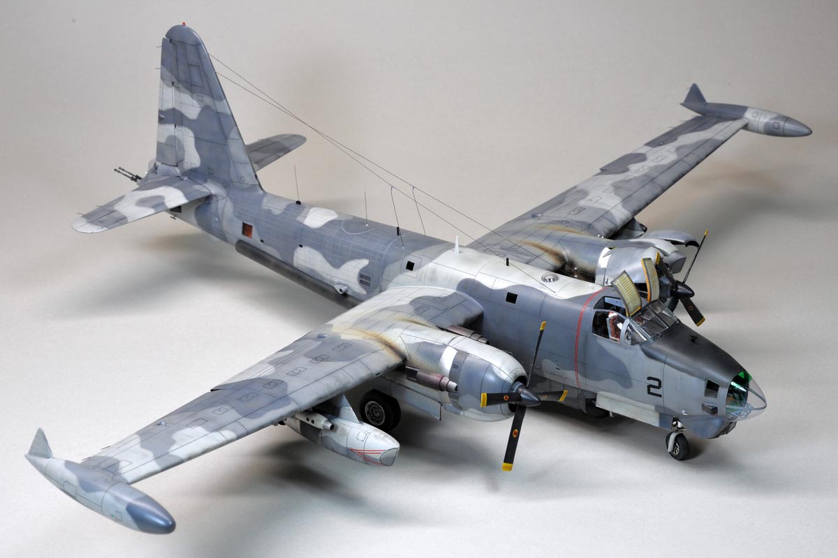
The AP-2H Neptune is a U.S.Navy's gunship deployed to South Vietnam (Cam Rahn Bay) between 1968 and 1969 with Heavy Attack Sqdn (VAH) 21.
A total of four AP-2Hs were highly modified P2V-7/SP-2H Neptune airframes carrying a big fuselage ASW radome with the MAD boom on the tail being removed entirely.
The top photo shows the major modifications applied on the P2V-7/SP-2H airframe, and I modified a Hasegawa P2V-7 kit (1/72) to the AP-2H configuration.
I considered using an AP-2H conversion kit from Blackbird models at the beginning. However, it was sold out, and I decided to scratch-built all the conversion parts by myself.
Apart from the conversions, I bought several after-market items including the followings.
1, Eduard photo-etched parts SS323
2, Plus Model Flaps set AL7019
3, Plus Model Racks AL7020
4, Plus Model Wheels AL7018
AP-2H僱僾僠儏乕儞偼暷奀孯偺VAH-21偑撿儀僩僫儉偺僇儉儔儞儀僀婎抧傪儀乕僗偵1968擭偐傜1969擭偵偐偗偰塣梡偝傟偨僈儞僔僢僾偱偡丅
寁係婡偺P2V-7傪戝暆偵夵憿偟偰AP-2H偼嶌傜傟傑偟偨偑丄P2V-7偺奜娤揑摿挜揰偱偁傞摲懱壓偺戝偒側ASW儗僪乕儉傗旜晹偵撍偒弌偟偨MAD僽乕儉偼庢傝奜偝傟傑偟偨丅
偦傟偵戙傢偭偰怴婯偵晅偗壛偊傜傟偨庡側憰旛昳偵偮偄偰忋偺幨恀偵楍嫇抳偟傑偟偨丅
塸崙偺Blackbird Models偐傜AP-2H偺夵憿僉僢僩偑敪攧偝傟偰偍傝丄摉弶偼偦傟傪巊偍偆偲巚偄傑偟偨丅
偟偐偟丄岾偐晄岾偐攧愗傟偵側偭偰偟傑偄丄暪偣偰偙偺夵憿僉僢僩偺宍忬偵擺摼偑偄偐側偐偭偨偨傔丄夵憰晹昳偼慡偰帺慜偱嶌傞偙偲偵偟傑偟偨丅
夵憿晹埵埲奜偵偼丄忋婰偺侾偐傜係傑偱偺暿攧晹昳傪峸擖偟偰巊偄傑偟偨丅
 One of the four AP-2Hs is still preserved and displayed at Pima Air Museum in Tucson, Arizona (See photo at left), and I took a lot of walkaround photos of this AP-2H in 2005 and in 2011,
The walkaround photos can be seen on my website by clicking on(HERE).
One of the four AP-2Hs is still preserved and displayed at Pima Air Museum in Tucson, Arizona (See photo at left), and I took a lot of walkaround photos of this AP-2H in 2005 and in 2011,
The walkaround photos can be seen on my website by clicking on(HERE).
Judging from the photos which I found on various websites, the AP-2Hs pictured at Cam Rahn Bay did not carry the US national markings, tail code(SL),
"NAVY" markings nor even Bureau number of the aircraft. So, I did not use any decals of those markings.
夵憿偝傟偨寁係婡偺AP-2H偺撪偺侾婡偑僺儅偺峲嬻攷暔娰偵曐懚丒揥帵偝傟偰偄傑偡(嵍幨恀嶲峫)丅彫惗偼2005擭偲2011擭偵僺儅傪朘栤偟丄AP-2H偺嵶晹幨恀傪戲嶳嶣偭偰偒傑偟偨偺偱丄
偦偺帪偺幨恀偼杮HP偺暿儁乕僕偵宖嵹偟偰偁傝傑偡丅(僐僐傪僋儕僢僋) .
僱僢僩偱AP-2H偑撿儀僩僫儉偱塣梡偝傟偰偄偨摉帪偺幨恀傪挷傋偰傒傑偟偨偑丄摉帪偼崙愋儅乕僋傗僥乕儖僐乕僪丄價儏儘乕斣崋丄峏偵偼NAVY偺昞婰傑偱徚偝傟偰偄偨傛偆偱偡丅
傛偭偰丄崱夞偼僨僇乕儖傪傎偲傫偳巊偄傑偣傫偱偟偨丅
You can enlarge all the photos on this page by clicking on images.
僋儕僢僋偱杮儁乕僕撪偺慡偰偺夋憸傪奼戝弌棃傑偡
Cockpit丂憖廲幒


(above 6 photos):
I added the arm rests(brass wire), the head rests(plastic with brass pins) and the seat cushions(plastic sheet) on the seat.
I used Eduard's colour photo-etched parts on the instrument panel, the center/side consoles and the seat belts.
The shape of the instrument panel part included in the kit is very wrong, so I remade it with plastic sheet.
亂忋6枃亃
嵗惾偼僉僢僩晹昳傪巊偭偰丄僿僢僪儗僗僩丄傂偠妡偗丄僋僢僔儑儞側偳傪捛壛偟偰丄偦傟傜偟偄宍偵偟傑偟偨丅
寁婍斦傗僐儞僜乕儖椶丄僔乕僩儀儖僩偼Eduard惢偺僇儔乕僄僢僠儞僌晹昳傪巊偭偰偄傑偡丅
僉僢僩晹昳偱偼僟僢僔儏儃乕僪傗寁婍斦偺宍忬偑偐側傝偍偐偟偄偺偱丄嶌傝捈偟傑偟偨丅
.
Canopy丂僉儍僲僺乕


(above 4 photos):
I removed the overhead hatchs and the side windows from the clear kit part, and I replaced them with press-formed clear part(PVC sheet),
because I finish the hatchs in open position and the side windows are very distorted.
I used Eduard photo-etched parts for the overhead console with the engine controles attached on the front portion.
The overhead hatch is a press-formed clear PVC sheet with the plastic frame painted in yellow.
The sunshade attached on the hatch is made of kitchen aluminium foil with parallel wrinkles.
亂忋4枃亃
僉僢僩偺摟柧僉儍僲僺乕晹昳偼丄惓柺偺巐妏暯柺晹偲拞墰揤堜晹乮幚婡偱偼晄摟柧晹乯傪巆偟偰慡偰愗傝庢傝傑偟偨丅
揤堜偺扙弌僴僢僠偼奐偗偨忬懺偱姰惉偝偣傞偨傔偲丄椉僒僀僪偺僶僽儖僂僀儞僪乕偼榗傒偑僸僪偐偭偨偨傔偱偡丅
愗傝庢偭偨晹暘偼丄0.3儈儕岤偺摟柧墫價斅傪峣偭偰抲偒姺偊傑偟偨丅
僆乕僶乕僿僢僪僐儞僜乕儖偼僇儔乕僄僢僠儞僌傪巊偄傑偟偨丅偦偺慜曽偵僗儘僢僩儖側偳偺僄儞僕儞惂屼梡儗僶乕傪晅偗傑偟偨偑丄
壗偣嫹偄応強側偺偱幚婡偺敿暘傕晅偄偰偄傑偣傫乮Ha-Ha両乯丅
揤堜僴僢僠偼峣偭偨墫價斅偺廃埻偵庽帀朹偱榞傪晅偗傑偟偨丅
榞偺拞偺擔彍偗梡僇乕僥儞(?)偼丄戜強偺傾儖儈僼僅僀儖偵暲峴偺僔儚傪晅偗偰嶌傝傑偟偨丅

.
Nose Section丂婡庱晹


(above 3 photos):
The nose clear part of the kit is heavily distorted, so I replaced the kit part with the press-formed nose made of 0.3mm PVC sheet.
Since I was not able to make a one-piece nose with the PVC sheet, I made two parts, the upper half and the lower half as shown on the photos above.
The upper part covers two rectanglar side windows on both sides.
亂忋3枃亃
僉僢僩偺摟柧晹昳偼偐側傝榗傫偱偄偨偺偱乮愭抂偼撌儗儞僘忬乯墫價斅偱峣傝傑偟偨丅
彫惗偺媄弍偱偼堦懱偱峣傟側偄偨傔丄忋敿暘偲壓敿暘偺俀晹昳偵暘妱偟傑偟偨丅
忋晹昳偵偼嵍塃偺巐妏偄彫憢傕堦懱壔偟傑偟偨丅


 (above 4 photos):
I made up the observer's compartment as shown on the above photos referencing some interior photos I found on the internet.
The footrest(?) is made of 0.3mm brass wire and fine plastic rods.
The fitting(mating) line of the upper and lower halves is hidden by using a decal strip placed over the line.(see photos below)
亂忋4枃亃
尒挘傝堳惾廃曈偼僱僢僩偱尒晅偗偨幚婡幨恀傪嶲峫偵偦傟傜偟偔揔摉偵嶌傝崬傒傑偟偨丅
懌妡偗(?)偺崪慻傒偼0.3mm恀鐹慄偺敿揷晅偗偱嶌傝丄彫巬(?)偼怢偽偟儔儞僫乕偱偦傟傜偟偔晅偗懌偟傑偟偨丅
忋敿暘偲壓敿暘偺摟柧晹昳偺崌傢偣儔僀儞偼丄嵶愗傝僨僇乕儖偱儃儘塀偟偟丄婡懱怓傪忋偐傜揾傝傑偟偨乮壓幨恀乯丅
.


.
Nose Landing Gear丂慜媟


 (these 3 photos):
Original kit parts of the nose gear assembly and the wheel well are too simple/basic as shown on the photo at left.
So, I scratch-built the whole wheel well with enough depth and width as shown on the photos above.
On the actual airplane, the nose gear strut is located on the center line of the airplane, but the well is offset to the right by appox. 3 inches.
So, I duplicated this design on my model.
亂忋3枃亃
巆擮側偑傜僉僢僩晹昳偱偼慜媟廂擺屔偼暆傕怺偝傕懌傝偢丄僨傿僥乕儖偼姰慡偵柍帇偝傟偰偄傑偡丅
媟拰峔惉傕嬌抂偵扨弮壔偝傟偰偄傑偡丅40擭埲忋偺慜偺僉僢僩偱偡偐傜丄巇曽側偄偱偡偹丅
偦偙偱媟屔偼100%嶌傝捈偟傑偟偨丅幚婡偱偼媟屔偑栺8僙儞僠塃懁偵僆僼僙僢僩偝傟偰偍傝乮媟拰偼偳恀傫拞乯偦傟傕嵞尰偝偣偨偮傕傝偱偡丅
.


(above 2 photos):
I added some details on the gear strut including the torque link (brass wire), the landing light, the side brace(right only) and the steering mechanism.
I finished the nose gear with the steering position slightly to the right.
I remade the wheel doors with uneven inner surface as shown on the above right photo.
亂忋2枃亃
僉僢僩晹昳偼媟拰傕僔儞僾儖夁偓傞偺偱丄嵍忋幨恀偺擛偔儔僀僩乮偝偐偮偆偺儔僀僩儗儞僘乯丄僩儖僋儕儞僋乮恀鐹慄乯丄巟帩朹乮塃偺傒乯丄僗僥傾儕儞僌儊僇側偳傪捛壛偟傑偟偨丅
幵椫偼塃曽岦偵彮偟僗僥傾儕儞僌傪愗偭偨忬懺偱嶌傝傑偟偨丅媟僇僶乕偼塃忋幨恀偺捠傝嶌傝捈偟丄撪懁偺撌墯傪嵞尰偝偣傑偟偨丅


Forward Fuselage丂慜晹摲懱


(above 2 photos):
The nose wheel well has been significantly deepened as explained above, and it results in the less space for the weight placed in the nose section.
So, I moved the wall befind the observer's seat forward to make some room befind it.
I placed a total of 40 gram weight in the limited space in the nose section as shown on the photo at above right.
亂忋2枃亃
慜媟廂擺屔傪怺偔偟偰丄峏偵憖廲惾偺彴傪俀儈儕壓偘偨寢壥丄怟傕偪杊巭梡偺僆儌儕傪巇崬傓僗儁乕僗偑傎偲傫偳柍偔側傝傑偟偨丅
偦偙偱丄巭傓柍偔尒挘傝堳惾屻傠偺暻傪彮偟慜偵弌偟偰丄僆儌儕乮栺40僌儔儉乯傪巇崬傓僗儁乕僗傪妋曐偟傑偟偨丅
Chin Fairing丂偁偛偺朿傜傒


(above 3 photos):
I made a wooden mould for the chin fairing and the press-formed fairing is made as shown on the above photos.
I made the LLLTV sensor and the FLIR sensor to install in the chin fairng.
亂忋3枃亃
偁偛偺僼僃傾儕儞僌乮偨傫偙傇乯偼栘宆傪嶌傝丄僾儔斅傪峣偭偰嶌傝傑偟偨丅
僼僃傾儕儞僌偺拞偵巇崬傓LLLTV僙儞僒乕偲FLIR僙儞僒乕偼丄傗偭偲扵偟摉偰偨幚婡幨恀傪嶲峫偵丄偦傟傜偟偔嶌傝傑偟偨丅


Search radar housing丂憑嶕儗乕僟乕


(above 5 photos):
The top two photos show the APQ-92 search radar which I pictured at Pima Air Museum.
At the beginning of modelling this search radar, I removed the large ASW radome from the kit parts, and I placed the plastic skin over the opening to smooth the surface.
The dark blue part pictured in the above photos is a cut-out piece of another Neptune kit picked from the area immediately aft of the bomb bay.
亂忋5枃亃
忋抜偺幨恀俀枃偼僺儅偺攷暔娰偱嶣偭偨幚婡偺APQ-92憑嶕儗乕僟乕偱偡丅
偙傟傪柾宆偱嵞尰偡傞偵摉偨傝丄傑偢偼僉僢僩偵晅偄偰偄傞戝偒側ASW儗僪乕儉傪愗傝庢傝傑偟偨丅
ASW儗僪乕儉偺戙傢傝偵憑嶕儗乕僟乕傪悩偊晅偗傞偨傔偺搚戜傪丄壓抜幨恀乮寁俁枃乯偺擛偔嶌傝傑偟偨丅
偙偙偵幨偭偰偄傞嵁怓偺晹昳偼丄暿僉僢僩偺敋抏憛捈屻偐傜愗傝弌偟偨傕偺偱偡丅


(above 3 photos):
I made up this search radar housing as shown on the photos above.
I used a cut-out piece of the wing tank part picked from Hasegawa's F-4 Phantom kit in 1/48 scale.
The hemispherical radome is a press-formed plastic sheet.
I scribed panel lines and rivet lines around the whole surface of the radar housing.
I added some details on the lower fuselage surface around the radar housing as shown on the photo at most right.
亂忋3枃亃
憑嶕儗乕僟乕偼忋偺幨恀偺擛偔偵嶌傝傑偟偨丅嬋柺晹偼1/48偺F-4僼傽儞僩儉丒僉僢僩偺梼壓憹憛偑悺朄揑偵僺僢僞儕偩偭偨偺偱丄偦傟傪愗偭偰棙梡偟傑偟偨丅
敿媴宍偺儗僪乕儉偼丄栘宆傪嶌偭偰丄僾儔斅偱峣傝傑偟偨丅幚婡偺儗乕僟乕晹昞柺偵偼懡偔偺僷僱儖儔僀儞傗儕儀僢僩儔僀儞偑妋擣偱偒傞偺偱挙傝崬傒傑偟偨丅
憑嶕儗乕僟乕廃曈偺摲懱壓柺偵偼怓乆側撌墯偑尒偊傞偺偱丄幚婡幨恀傪嶲峫偵嵍忋幨恀偺擛偔偦傟傜偟偔嶌傝崬傒傑偟偨丅


SLAR Fairing SLAR僼僃傾儕儞僌


 (these 3 photos):
The SLAR fairing is simple and easy to make up.
I used a plastic pipe and I cut it in half at first.
Epoxy putty is applied at the both ends of the half-pipe and I sanded the both ends into the spherical shape as shown above.
I'm afraid I was not able to find any good close-up photos of the SLAR fairing,
so the shape I made up could be wrong.
I added some modifications around the fairing as shown on the top right photo.
亂忋3枃亃
SLAR僼僃傾儕儞僌偼扨弮偱娙扨側岺嶌偱偟偨丅
庽帀僷僀僾傪敿暘偵妱偄偰丄偦偺椉抂偵僄億僉僔僷僥傪杽傔崬傒傑偟偨丅
椉抂偼媴忬偵嶍傝崬傫偱弌棃忋偑傝偱偡偑丄偙偺晹暘偺幚婡奼戝幨恀偑尒晅偐傜偢丄
偙偙偺宍忬偼娫堘偭偰偄傞偐傕抦傟傑偣傫丅
偙偺僼僃傾儕儞僌偺廃曈偵偼AP-2H撈摿偺彫偝側夵憿偑巤偝傟偰偍傝丄塃忋幨恀偺擛偔捛壛岺嶌傪偟傑偟偨丅
.

Tail Section丂旜晹


 (these 3 photos):
The top two photos show the tail section of the actual AP-2H Neptune preserved at Pima Air Museum.
I cut off the tail section of the kit part into three pieces as shown on the photo at bottom left, and I discarded the MAD boom portion.
亂忋3枃亃
忋抜偺俀枃偺幨恀偼僺儅偺攷暔娰偱嶣塭偟偨幚婡偺旜晹偺僋儘乕僘傾僢僾偱偡丅
偙偺幨恀偺傛偆偵夵憿偡傞偨傔丄壓抜嵍幨恀偺擛偔僉僢僩偺旜晹傪愗抐偟偰丄旜抂偺MAD僽乕儉偼幪偰傑偟偨丅
.


(above 3 photos):
The cross-sectional shape of the tail end of the kit part is too narrow as shown on the photo at above right.
So, I inserted the wedge-shaped spacer in between lower fuselage halves to widen the tail cross-section.
I glued the press-formed clear part (tail gunner's window) on the top of this tail part, and the opening at the tail end was blocked with epoxy putty as shown above.
亂忋3枃亃
僉僢僩晹昳偺旜晹廵嵗曈傝偺摲懱抐柺宍忬傪嵍忋偺幨恀偱偛棗偔偩偝偄丅
梋傝偵傕嵶夁偓傞偺偱丄媴宍偺廵嵗僞乕儗僢僩偑庢傝晅偗弌棃傑偣傫丅
偦偙偱丄旜晹摲懱偺嵍塃晹昳偺娫偵僗儁乕僒乕(嵟戝2.5儈儕掱乯傪偐傑偣偰丄墶暆傪峀偘傑偟偨丅
摲懱暆偺曄壔傪僗儉乕僘偵偡傞偨傔偵丄壓懁偺僗儁乕僒乕偼僋僒價宍偵偟傑偟偨丅
旜抂偺奐岥晹偼僄億僉僔僷僥偱杽傔傑偟偨丅


 (these 3 photos):
The gun barrel is made mainly of brass pipes in three different diameters as shown above.
I glued the cone-shaped aluminium pope at the tip of the barrel
A photo at bottom left shows the orange & white lights placed on the tail section.
亂忋3枃亃
廵恎偼宎偺堎側傞俁庬椶偺恀鐹僷僀僾傪偮側偄偱嶌傝傑偟偨丅
儔僢僷忬偺愭抂晹偼丄傾儖儈僷僀僾傪壛岺偟偰嶌傝傑偟偨丅
壓抜嵍偺幨恀偼丄旜晹偵庢傝晅偗傜傟偨僆儗儞僕偲敀偺儔僀僩偱偡丅
偙傟傪72攞偺戝偒偝偵偟偨傜丄幚婡偺儔僀僩偵斾傋偰俀攞埲忋偺戝偒偝偵側傝傑偡(Ha-Ha両)丅
.


R-3350 Engine丂R-3350僄儞僕儞


(above 2 photos):
I wanted to finish my model with the left engine covers in the open position.
So, I bought the resin set of the R-3350 engine from "Plus Model"(see photo at abouve left).
I put additional details by using brass wire and nickel silvcer wire as shown on the above right photo.
亂忋2枃亃
嵍梼偺僄儞僕儞偼僇僶乕傪奐偗偨忬懺偱嶌傠偆偲丄曅懁偩偗偼僾儔僗儌僨儖偺儗僕儞僉僢僩傪攦偭偰偒傑偟偨乮嵍忋幨恀乯丅
塃忋偺幨恀偼偦傟傪慻傒忋偘偨傕偺偱偡偑丄恀鐹慄傗梞敀慄傪巊偄嵶晹傪偦傟傜偟偔捛壛偟傑偟偨丅


(above 4 photos):
I recreated the engine covers with thin (0.3mm) plastic sheet by the heat-press process.
The mould of the process was made of the kit part with epoxy putty.(see photo at top left)
I assembled the covers (a total of four) as shown on the top right photo.
The turbo charger parts (see photo at bottom left) were glued at the three exhaust locations.
The support rod (brace) for the upper three covers is 0.3mm nickel silver wire (the bottom right photo).
亂忋4枃亃
僄儞僕儞僇僶乕偼係暘妱偝傟偰偍傝丄偄偢傟傕0.3儈儕岤僾儔斅傪峣偭偰昞柺晹暘傪惉宍偟傑偟偨丅
宆偼僉僢僩晹昳傪偦偺傑傑巊偄丄撪懁傪僄億僉僔僷僥偱曗嫮偟傑偟偨丅忋俁枃偲壓侾枃偼暿乆偺宆傪巊偄傑偟偨乮忋抜嵍幨恀乯
忋偺僇僶乕俁枃偺廃埻偵偼榞傪晅偗傑偟偨丅壓偺僇僶乕偼擇廳峔憿偺傛偆偵側偭偰偍傝丄峣偭偨僇僶乕偺俀枃傪彮偟僘儔偟偰愙拝偟傑偟偨丅
側傫偪傖偭偰僞乕儃僠儍乕僕儍乕傪俁偮嶌傝丄攔婥娗埵抲偵慻晅偗傑偟偨乮壓抜嵍幨恀乯丅
忋俁枃偺僇僶乕偺巟帩梡亀偮偭偐偊朹亁偼0.3儈儕偺梞敀慄傪巊偄傑偟偨乮壓抜塃幨恀乯


(above 3 photos):
The flame dampenner was made up with three press-formed and cylindrical-shaped parts as shown on the most left photo.
The three layers of the press-formed parts were glued together as shown on the middle photo.
I attached a total of three flame dampeners on the right engine nacelle at the exhaust pipe location.
亂忋3枃亃
忋偺幨恀偺擛偔丄宎偺堎側傞敿墌摏宍偺晹昳傪俁庬椶峣偭偰丄偦傟傜傪廳偹崌傢偣傞偙偲偱徚墛儅僼儔乕傪嶌傝傑偟偨丅
徚墛儅僼儔乕偼塃僄儞僕儞偺俁偐強偺攔婥娗偺忋偵屌掕偟傑偟偨丅乮塃忋幨恀乯


(above 3 photos):
The most left photo shows the mounting bracket for the flame dampener which I pictured at Pima Air Museum.
I made up this small part as shown on the middle photo.
I glued a total of six(three pairs) brackets on the left engine nacelle (most right photo).
亂忋3枃亃
嵍抂偺幨恀偼徚墛儅僼儔乕傪庢傝晅偗傞偨傔偺僽儔働僢僩偱偡丅僺儅偺攷暔娰偱嶣塭偟傑偟偨丅
嵍僄儞僕儞偺僇僶乕偼奐偗傞偺偱丄徚墛儅僼儔乕偼晅偗偢丄戙傢傝偵偙偺僽儔働僢僩偩偗傪慻傒晅偗傞偙偲偵偟傑偟偨丅
偙偺彫偭偪傖偄晹昳偼恀傫拞偺幨恀偺擛偔丄僠儅僠儅偲嶌傝傑偟偨丅
偦傟傜傪嵍僄儞僕儞僫僙儖偵庢傝晅偗偨幨恀偑塃抂偱偡丅

Main Landing Gear丂庡媟


(above 4 photos):
To make enough space/room in the forward portion of the main wheel well, I cut off the portion I marked on the top left photo.
Hasegawa kit does not have any details inside the wheel well, so I added a lot of details as shown on the remainning three photos.
I placed the thin lead sheet with pararell lines scribed on both sides of the walls and the upper wall inside the forward wheel well.
亂忋4枃亃
媟廂擺屔偺慜敿暘偵偼幵椫偑廂傑傝傑偡偑丄僉僢僩晹昳偱偼偦偺僗儁乕僗偑嫹偡偓傞偨傔丄忋抜嵍偺幨恀偱幬慄偱埻偭偨晹暘傪愗傝庢傝傑偟偨丅
僉僢僩晹昳偱偼廂擺屔撪晹偵堦愗偺僨傿僥乕儖偑柍偄偺偱丄忋偺幨恀偺擛偔僠儅僠儅偲撪晹傪嶌傝崬傒傑偟偨丅
媟屔慜敿暘偺撪懁偺暻乮椉懁柺偲忋柺乯偵偼丄敄偄墧斅偵宺慄傪偗偑偄偰丄揬傝崬傒傑偟偨丅


 (these 3 photos):
Hasegawa kit has the main landing gear mislocated in its wheel well.
A photo at bottom left shows the P2V-7's main landing gear viewed from the front.
As you can see from the photo, the strut is offset to the inboard side in its wheel well.
However, the strut of the kit is located in the center of the wheel well.
So, I corrected the shape of the strut part as shown on the photo at top left.
I added the hydraulic lines (brake pipes) on the back side of the strut (see top right photo) with 0.2mm brass wire.
亂忋3枃亃
壓抜嵍偺幨恀偼P2V-7幚婡偺塃庡媟傪惓柺偐傜嶣傝傑偟偨丅媟拰偼撪懁乮幨恀偱偼塃懁乯偵僆僼僙僢僩偟偰庢傝晅偗傜傟偰偄傑偡丅
偟偐偟丄僴僙僈儚偺僉僢僩偱偼媟拰偑恀傫拞偐傜棫偭偰偍傝丄廋惓偑昁梫偲側傝傑偟偨丅
忋抜嵍偺幨恀偺擛偔丄媟拰偼撪懁偵曅婑偭偨宍忬偵廋惓偟傑偟偨丅
僽儗乕僉僷僀僾乮俁杮乯偼媟拰偺屻傠懁偵0.2儈儕偺恀鐹慄偱庢傝晅偗傑偟偨乮忋抜塃幨恀乯
.

Flap丂僼儔僢僾


(above 4 photos):
I used the flap set of "Plus Model"(top left photo) and I finished my model with its flaps in lowered position.
I wondered what was the color on the upper surface of the AP-2H flap, and I founld only one photo on the internet.
It was painted in camouflage colour of three tones of grey(bottom left photo).
亂忋4枃亃
僼儔僢僾偼壓偘偰嶌傞偺偑岲偒側彫惗偼丄僾儔僗儌僨儖偺僼儔僢僾僙僢僩傪攦偭偰偒傑偟偨乮忋抜嵍幨恀乯丅
僄僢僠儞僌僷乕僣偺慻棫偰偼偐側傝庤娫偑妡偐傞偟丄僉僢僩晹昳偲偺崌傢偣崬傒傕柺搢側嶌嬈偱偟偨丅
偦傟偱傕弌棃忋偑偭偰偟傑偊偽枮懌偱偡丅僼儔僢僾偺忋柺偺揾憰怓偵偼摉弶擸傫偩偺偱偡偑丄僱僢僩偱偨偭偨侾枃
僼儔僢僾偺忋柺偑幨偭偨幨恀傪尒晅偗丄偦偙傕柪嵤揾憰偲敾柧偟傑偟偨丅
Engine Nacelle丂僄儞僕儞僫僙儖


 (these 3 photos):
I took the top left photo at Pima museum, and as you can see from the photo, the top surface of the engine nacelle is smoothly-curved surface.
However, the kit part, as shown on the bottom left photo, has edged (not soft) surface.
So, I applied putty at the edged area (see the upper part of the bottom left photo) to smoothen the surface.
亂忋3枃亃
忋抜嵍偺幨恀偼僺儅偺攷暔娰偱嶣傝傑偟偨偑丄僄儞僕儞僫僙儖忋柺偲庡梼忋柺偑梈崌偡傞柺偼妸傜偐偵僇乕僽偟偰偄傞帠偑傢偐傝傑偟偨丅
僴僙僈儚偺僉僢僩晹昳偱偼丄偦偺晹暘偑偔傃傟偰偍傝乮妏忬偵側偭偰偍傝乯丄崌傢偣晹偵僗僕偑捠偭偰偄傑偡乮壓抜嵍幨恀偺壓敿暘乯丅
偦偙偱丄偔傃傟偰偄傞晹暘偵僷僥傪惙傝乮壓抜嵍幨恀偺忋敿暘乯丄妸傜偐側嬋柺偵廋惓偟傑偟偨丅
.
Wing-tip Tank丂梼抂僞儞僋


(above 4 photos):
I noticed that the wing-tip tank is angled slightly (3 or 4 degrees) upward and it looked quite strange as shown on the top left photo.
So, I changed the mounting angle between the wing-tip and the tank.
I cut off the wing tip and I filled the dent of the tank with putty.
Then, I joined these two pieces by using the brass pipe (wing side) and the brass wire (tank side) as shown on the top right photo.
The bottom right photo shows the result of the modification, and the tank is quite level at the end.
亂忋4枃亃
梼抂僞儞僋傪庢傝晅偗偰傒偨傜丄慜抂偑彮偟乮俁乣係搙丠乯忋岦偒偵側偭偰偟傑偄丄偐側傝晄帺慠偵姶偠傑偟偨乮忋抜嵍幨恀乯丅
偦偙偱丄梼抂偺僞儞僋嵎偟崬傒晹傪愗傝庢傝丄暪偣偰僞儞僋偺墯傒晹傪僷僥偱杽傔傑偟偨丅
椉幰偼恀鐹慄乮僞儞僋懁乯偲恀鐹僷僀僾乮梼抂偺庴偗懁乯傪巊偄丄僞儞僋偑悈暯偵側傞傛偆偵庢晅妏搙傪廋惓偟傑偟偨丅
壓抜塃懁偺幨恀偼夵廋屻偺巔偱偡偑丄僞儞僋偼傑偁傑偁悈暯偵側傝傑偟偨丅


(above 2 photos):
I used "clear epoxy cemment" to make the navigation light, and I applied a very small amount of the cemment on the outboard surface of the tank (above left photo).
I painted clear Green or clear Red on the forward half of the light and I painted grey on the rear half of the light fairing.
I found the AP-2H photo with its search light lens on the wing-tip tank was painted over, so I painted over the clear part of the light in camouflage grey.
亂忋2枃亃
梼抂僞儞僋偺奜懁偵彫偝側峲朄摂偑晅偄偰偄傑偡丅
偦傟偼摟柧僄億僉僔僙儊儞僩傪巊偄丄傢偢偐側検傪僞儞僋懁柺偵揰晅偗偟傑偟偨丅
姡憞偟偰偐傜丄慜敿暘傪椢偐愒偵丄屻傠敿暘傪柪嵤僌儗乕偵揾傝傑偟偨丅
傑偨丄P-2偺塃僞儞僋偺慜抂偵偼憑嶕儔僀僩偑晅偄偰偄傑偡偑丄AP-2H偺幨恀傪挷傋傞偲儔僀僩偑奜偝傟偰偄傞婡懱傕桳偭偨偨傔丄儔僀僩偺摟柧晹昳偼柪嵤怓偱揾傝偮傇偟傑偟偨丅
Other Small Parts丂懠彫暔晹昳


(above 2 photos):
I made up the jet engine silencer with thin plastic sheet as shown on the above photos.
I rolled the thin plastic sheet into the cylindrical shape by soaking the sheet in the hot water.
亂忋2枃亃
僕僃僢僩僄儞僕儞偺徚壒儅僼儔乕偼敄偄僾儔斅傪娵傔偰嶌傝傑偟偨丅
娵傔偨忬懺偱擬搾偵偮偗偰丄墌摏宍傪嶌傝傑偟偨丅
奺墌摏偺抂晹偼彮偟斀傝忋偑偭偰偄傞傛偆側偺偱丄抂柺偵僾儔偺椫傪晅偗偰嶍傝傑偟偨丅


(above 2 photos):
I used the plastic pipe to make up the minigun and I used the plastic sheet to make the pylon for the minigun.
The minigun is mounted under the pylon pointing slightly downwards.
亂忋2枃亃
庡梼壓偺儈僯僈儞偼庽帀僷僀僾傪壛岺偟偰嶌傝傑偟偨丅
偪傚偆偳椙偄宎偺儌僲偑柍偐偭偨偺偱丄偪傚偭偲懢傔偱偡丅
僾儔斅傪愗傝弌偟偰嶌偭偨僷僀儘儞偼丄儈僯僈儞庢晅晹偑彮偟壓岦偒偵側偭偰偄傑偡丅
Riveting丂儕儀僢僩懪偪


(above 4 photos):
The rear half of the fuselage and the bomb bay door have raised rivets as shown on the top left photo.
So, I engraved the rivet lines on the rear fuselage by using the UMM-USA's riveting tool as shown on the top right photo.
The UMM-USA's tool worked very good, and they carried the single, double and even triple wheels.
Naturally, I used the single wheel tool on most of the surface.
亂忋4枃亃
僱僾僠儏乕儞偱偼摲懱偺屻傠敿暘偲敋抏憛僪傾偵撌儕儀僢僩偑巊傢傟偰偄傑偡乮忋抜嵍幨恀乯丅
偦偙偱丄偦傟傪嵞尰偡傞偨傔偵丄彫惗偑垽梡偟偰偄傞UMM-USA幮偺僐儘僐儘幃儕儀僢僩懪偪岺嬶傪巊偄丄屻晹摲懱傗敋抏憛僪傾偵儕儀僢僩傪懪偪傑偟偨丅
忋抜塃幨恀偺擛偔UMM-USA幮偱偼丄僐儘僐儘偡傞帟幵偑侾枃偺傕偺偩偗偱側偔丄俀枃丄俁枃偺岺嬶傕斕攧偟偰偄傑偡丅
彫惗偼僐儘僐儘偡傞帪偵僈僀僪偼巊傢偢丄帠慜偵墧昅偱壓彂偒偟偨慄偵増偭偰丄僼儕乕僴儞僪偱揮偑偟偰偄傑偡丅
僈僀僪傪摉偰傞偲恘愭偑塀傟傞偺偱惓妋偵揮偑偣側偄偨傔偱偡丅
Masking丂儅僗僉儞僌


 (these 3 photos):
I used the thin(0.2mm) lead sheet of 17mm width as masking material.
I bought it at a fishing tackle store beuause it is used as a sinker for fishing.
This material fits to various curved surfaces very easily.
Also, you can easily control the gap between the surface of the model and this masking material at any curved surfaces by using toothpick as shown on the top right photo.
It means you can easily control the softness of the two colors at the border.
If you want to cover much broader area with this material, you can joint this plate(17mm width) side by side by using adhesive tape to widen the covering area.
亂忋3枃亃
嫬奅慄傪傏偐偡柪嵤偺揾憰偵偼丄掁傝梡偺挿姫斅僆儌儕乮栺0.2mm岤丄17mm暆偺墧儕儃儞乯傪儅僗僉儞僌嵽偲偟偰巊偭偰偄傑偡丅
挿強偼庡偵擇偮桳傝傑偡丅
堦偮栚偼嶰師尦嬋柺偵椙偔撻愼傫偱偔傟傑偡丅
庡梼忋柺偺傛偆側暯柺偱偼丄偁傑傝偙偺挿強偼惗偐偝傟傑偣傫偗偳丅
擇偮栚偺挿強偼丄柪嵤怓娫偺儃働暆傪僐儞僩儘乕儖偡傞僗僉娫傪丄偨偲偊嬋柺忋偱偁偭偰傕丄堦掕偺悺朄偵懙偊傞偺偑娙扨偱偡丅
捾梜巬偺愭抂傪僗僉娫偵嵎偟崬傫偱挷惍偟偰傑偡乮忋抜塃幨恀乯丅
場傒偵丄抧尦崈憙巗偺彫偝側掁嬶揦偱偙偺斅僆儌儕偺挿姫乮懡暘80儊乕僩儖乯傪攦偆偲1600墌埵偱偟偨丅
暆峀偔儅僗僉儞僌偟偨偄応崌偼丄偙偺斅僆儌儕傪墶暆曽岦偵俀枃偲偐俁枃偲偐僙儘僥乕僾偱晅偗偰暆傪峀偘傜傟傑偡丅
Finally completed丂偮偄偵姰惉


Indoor Photography丂壆撪嶣塭


Under surface丂壓柺


Afterword丂偁偲偑偒
 I recently bought an unique camera called "Snake Camera" as shown on the left photo.
This is an endoscope camera for industrial use, and it has a small lens and a LED light at the end of the the long camera probe.
The reason why I bought it is I wanted to take a close-up photo of the inside details of the landing wheel well.
It was not so expensive, and it cost me 9,500yens (appox.90.00USD).
Now I'm able to take good close-up photos of dark landing wheel well, cabin and cockpit interior or any small parts placed in a dark area.
You can even take photos inside of the nostrils (Ha-Ha !). Anyway, I used some snake camera photos on this page.
I recently bought an unique camera called "Snake Camera" as shown on the left photo.
This is an endoscope camera for industrial use, and it has a small lens and a LED light at the end of the the long camera probe.
The reason why I bought it is I wanted to take a close-up photo of the inside details of the landing wheel well.
It was not so expensive, and it cost me 9,500yens (appox.90.00USD).
Now I'm able to take good close-up photos of dark landing wheel well, cabin and cockpit interior or any small parts placed in a dark area.
You can even take photos inside of the nostrils (Ha-Ha !). Anyway, I used some snake camera photos on this page.
Hasegawa's P2V-7 kit was released more than forty years ago, so it has the raised panel/rivet lines and the kit parts do not have good details at all.
However, the outline of the airframe is fairly good and this was a very good kit as a base of my AP-2H project.
I did make a quite good survey of the AP-2H at Pima Air Museum and I took a lot of walkaround photos including the upper surface of the wing.
However, the museum aircraft did not have the SLAR firling, the jet engine silencer nor the flame dampener on the airframe.
To make matters worse, I was not able to find any good close-up photos of the above-mentioned equipments, so the shape of them should not be very correct, I'm afraid.
In any case, I enjoyed the AP-2H project so very much from the beginning (survey at Pima museum) till the end with the snake camera.
As a matter of fact, I started building the AP-2H model in March 2020, and due to the Corona/China virus crisis I had to stay home for whole three months.
So, the progress of this project has been much faster than other projects, fortunately!.
嵟嬤柺敀偄僇儊儔傪攦偄傑偟偨丅僗僱乕僋僇儊儔偲屇偽傟偰偄傑偡丅
愜妏嬯楯偟偰嶌傝崬傫偩媟廂擺屔偺拞傪偪傖傫偲嶣傝偨偔偰怓乆偲峫偊傑偟偨丅
偦偙偱儕儞僌僼儔僢僔儏傪攦偍偆偐偲僱僢僩偱挷傋偰偄傞撪偵丄僗僱乕僋僇儊儔偲弌夛偄傑偟偨丅
傑偁9,500墌側傫偱偦傫側偵崅偔側偄偟丄傑偁僀僀偐側偲億僠傝傑偟偨丅
岺嬈梡偺撪帇嬀僇儊儔偲偟偰斕攧偝傟偰偍傝丄挿偄僾儘乕僽偺愭抂偵偼捈宎8儈儕偺摏偺拞偵儗儞僘偲LED儔僀僩偑巇崬傑傟偰偄傑偡丅
摓拝屻憗懍嶣偭偰傒傑偟偨丅僐儗偑側偐側偐柺敀偄偟丄椙偔嶣傟傞丅
埨暔側傫偱夋幙偼僜僐僜僐偱偡偑丄HP偵宖嵹偡傞幨恀偲偟偰偼廩暘偱偡丅
偙偺儁乕僕偵傕僗僱乕僋僇儊儔偺夋憸傪寁10枃巊偄傑偟偨丅
偝偰丄僴僙僈儚偺P2V-7偺僉僢僩偼敪攧偝傟偰偐傜係侽擭埲忋宱偪傑偡丅
傛偭偰丄僷僱儖儔僀儞偼撌儌乕儖僪偩偟丄嵶晹偺僨傿僥乕儖偑傎偲傫偳儌乕儖僪偝傟偰偄傑偣傫丅
傛偭偰尰嵼偺栚偱尒傟偽弌棃偺埆偄僉僢僩偐傕抦傟傑偣傫偑丄奜娤宍忬偼偐側傝偪傖傫偲偟偰偄傞偺偱丄
彫惗偵晄枮偼桳傝傑偣傫丅崱夞偺AP-2H僾儘僕僃僋僩偺儀乕僗偲偟偰偼廩暘側弌棃偺僉僢僩偱偟偨丅
偙偺僾儘僕僃僋僩偼2005擭偵僺儅偺攷暔娰偱AP-2H偺嵶晹幨恀傪嶣偭偨帪偐傜巒傑傝傑偟偨丅
庡梼偺忋柺傕嶣塭偟偨偐偭偨偺偱丄媟棫偲堦媟乮帺嶣傝朹傛傝偢偭偲挿偄両乯傪巊偄丄偐側傝慛柧偵嶣傟傑偟偨丅
僴僙僈儚偺僉僢僩偺僷僱儖儔僀儞偑幚婡偲慡慠堘偆偙偲傕幨恀偐傜傢偐傝傑偟偨丅
僺儅偺揥帵婡偵偼SLAR僼僃傾儕儞僌傗僕僃僢僩僄儞僕儞偺徚壒儅僼儔乕傗R-3350偺徚墛儅僼儔乕傕晅偄偰偄傑偣傫丅
僱僢僩偱挷傋偰傕丄偦傟傜偺慛柧側徻嵶幨恀偼尒晅偐傜偢丄巭傓柍偔亀側傫偪傖偭偰晽亁偵偦傟傜偟偔嶌傝傑偟偨丅
偲偙傠偱丄偙偺AP-2H傪嶌傝巒傔偨偺偼2020擭俁寧偱偟偨丅惓偵僐儘僫價乕儖僗偑枲墑偟巒傔偨僞僀儈儞僌偱偡丅
偦偺屻俁偐寧娫偼偢偭偲"Stay Home"偟偰偄偨偺偱丄捠忢傛傝傕攞偺僗僺乕僪偱嶌嬈偼恑傒傑偟偨丅
傛偭偰丄捠忢側傜俉乣10偐寧妡偐傞惢嶌偑傢偢偐俆偐寧偱姰惉偟傑偟偨丅
偄偢傟偵偟偰傕丄僺儅偱偺挷嵏偐傜僗僱乕僋僇儊儔偱偺嶣塭傑偱丄偲偰傕妝偟偔偰廩幚偟偨AP-2H僾儘僕僃僋僩偱偟偨丅
.